10 Nov 2026
Solving ATE Challenges with High-Density PXI/PXIe Arbitrary Waveform Generators
By Tom Sarfi
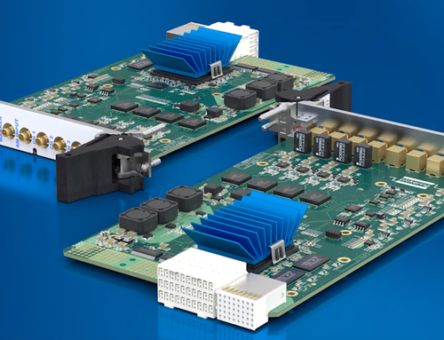
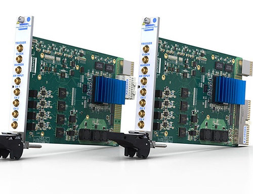
The Pickering 41–621 (PXI) and 43–621 (PXIe) arbitrary waveform generators pack up to four channels into a single 3U slot, the highest channel density above 20 MHz in their class. This high channel density, combined with approximately 40% lower per-channel costs and compatibility with both PXI and Pickering’s LXI/USB modular chassis, helps engineers overcome space constraints, budget pressures, and obsolescence risks. These advantages are particularly valuable in applications such as avionics functional testing, FADEC testing, multi-channel sensor simulation, and legacy ATE modernization.
Engineers building automated test systems for defense and automotive programs face a familiar set of constraints, including limited chassis slots, tightening budgets, and aging platforms that need to support new devices under test (DUTs) without a full rebuild. Waveform generation sits at the center of many of these systems, and when the instrumentation driving that stimulus consumes more rack space and budget than it should, the whole test strategy suffers.
The 41-621 and 43–621 arbitrary waveform generators were designed to address exactly this challenge. By doubling the channel count available in a single slot and extending this across both PXI and LXI platforms, these modules give engineers greater system design flexibility without the usual trade-offs in cost or footprint.
Why Channel Density and Chassis Flexibility Matter for ATE Design
Every PXI-based automated test system is, in some sense, a negotiation over how to deploy available slots. Each additional instrument adds cabling, chassis real estate, and cost. For engineers scaling up multi-channel simulation, this negotiation becomes a real constraint if a system needs more than one or two independent waveform channels. That would typically require additional modules and slots, which can compound quickly across chassis count and overall system price.
How High-Density PXI Waveform Generators Reduce ATE Slot Count and Cost
Our latest waveform generators deliver up to four independent channels in a single 3U slot, the highest PXI/PXIe channel density available above 20 MHz in their class. Each channel generates sine, square, triangle, ramp, and user-specified arbitrary waveforms at frequencies up to 40 MHz, with 1 µHz frequency resolution referenced to the 10 MHz PXI clock, a 1 ppm internal clock, or an external standard.
Doubling the channel count per slot directly affects system architecture: a reduced slot count allows additional functionality to fit within the chassis, leading to a smaller system footprint, lower power draw, and lower system cost. We estimate this density advantage our four-channel module offers translates to approximately a 40% lower cost per channel compared to competing solutions, a figure that matters when budget allocation for test systems is under scrutiny.
How does dual-platform support reduce integration risk?
Dual-format modules support two chassis paths. The 41–621 runs in standard 3U PXI or CompactPCI chassis, legacy and hybrid PXIe slots, or Pickering's LXI/USB modular chassis. The 43–621 runs in any 3U PXIe-compliant chassis, in both PXIe and hybrid slots. System architects will opt for an LXI interface when remote control and ease of communication over LAN are desired. PXI or PXIe may be selected when tighter timing and synchronization are required in a multi-vendor environment. Whether a PXI/PXIe or LXI chassis is used, a common API is used to communicate with the module, providing maximum flexibility in system design while minimizing non-recurring engineering effort.
What software and driver support does the module include?
We supply kernel and VISA drivers, as well as a soft front panel for quick configuration. Drivers support NI products, including LabVIEW, TestStand & VeriStand, as well as other popular programming environments such as Python, C/C++, C#, .NET, and MathWorks MATLAB & Simulink. This breadth matters for engineers integrating new instrumentation into an existing software stack, as it does not require them to use a specific language to utilize the module's full functionality.
Technical Capabilities That Address Common ATE Design Challenges
How do these modules generate complex stimulus without added instrumentation?
Each channel combines continuous-phase direct digital synthesis (DDS) with a 16-bit DAC that updates at up to 250 MS/s. In DDS mode, it produces sine waves to 40 MHz and square, triangle, and sawtooth waveforms to 20 MHz. In arbitrary waveform (ARB) mode, each channel draws on up to 128 MS of onboard memory, with disk streaming supported at rates up to 1 MS/s.
Built-in modulation and sweep capabilities set the module apart for complex stimulus generation. Each channel supports AM, FM, FSK, ramped FSK, PSK, PWM, OOK, and chirp, driven by either an external input or an internal waveform. Linear sweeps, swept-carrier AM, and a 512-entry custom sweep table (frequency and dwell time) are also available. This functionality lets engineers replicate realistic sensor transients or exercise a control loop over a non-linear frequency ramp without a separate function generator or signal-conditioning stage.
External clock and trigger inputs, or the PXI backplane triggers, let you synchronize and phase-align channels within a module and across multiple modules. This capability is essential for multi-channel simulation applications, where relative phase between channels carries diagnostic meaning, not just amplitude or frequency accuracy.
What output performance can engineers expect?
The module outputs up to 20 Vpp into an open load (or 10 Vpp into 50 ohms), with 16-bit resolution. DC accuracy is rated at ±0.55% of setting, ±5 mV, with AC accuracy of ±0.2% typical below 100 kHz. Total harmonic distortion remains below -78 dBc up to 100 kHz, then degrades to -55 dBc at 10 MHz and -38 dBc at 40 MHz. Spurious-free dynamic range holds at 70 dBc or better from 10 MHz to 40 MHz. Crosstalk between channels is specified at -100 dB across the full DC-to-40 MHz range, a figure that is directly relevant to multi-channel sensor simulation, where channel-to-channel isolation prevents one simulated signal from corrupting another.
Trigger support includes PXI_TRIG backplane triggers, software triggers, and front-panel triggering, with start, stop, reset, and N-shot modes available. Typical trigger latency from the SMB input is 440 ns with 8 ns typical jitter, numbers that matter when synchronizing stimulus generation to an external event in a closed-loop test.
Why does channel density matter for avionics functional test?
Avionics functional test systems often need to simultaneously stimulate multiple independent signal paths to replicate the analog outputs of flight-control sensors, actuator feedback loops, or communication-bus interfaces under test. A test engineer building an avionics functional tester benefits directly from fitting four channels into a single slot: a system requiring 16 channels of stimulus needs only four 41–621 modules instead of eight two-channel equivalents, cutting the chassis slot count in half and simplifying the interconnect cabling.
Supporting FADEC System Testing
Full authority digital engine control (FADEC) system testing requires generating precise, often time-varying signals that replicate sensor inputs, such as simulated speed-sensor pulses or pressure-transducer outputs, which are fed into the engine controller under test. The 41–621's ability to generate frequency sweeps, chirps, and custom modulation patterns from a 512-entry frequency-and-dwell-time table allows engineers to replicate transient engine conditions, such as an accelerating turbine-speed signal, without external signal conditioning. Phase alignment across channels supports coordinated multi-sensor stimulus, which matters when a FADEC under test correlates readings across several simulated inputs simultaneously.
Making Multi-Channel Transducer and Sensor Simulation Easier
System test engineers consistently report a need for simulation products that cover a wide frequency range and share excitation across multiple simulated devices without requiring a separate instrument for each device. The 41–621's four channels per slot, combined with -100 dB crosstalk isolation and multi-module phase synchronization, directly addresses this requirement. One module can drive several independent simulated sensor channels while preserving the isolation needed to validate a controller's response to each signal independently, including fault conditions introduced through modulation or signal interruption.
Legacy ATE Refresh and Rehost Projects
Legacy ATE refresh projects carry a specific risk profile: test engineers need to replace aging, often obsolete instrumentation while preserving existing test code, fixtures, and qualified test sequences wherever possible. The 41–621's support for both PXI and Pickering's LXI/USB modular chassis gives engineers a rehost path without forcing a wholesale change in chassis architecture. A system originally built around PXI can extend to LXI-based subsystems, or vice versa, while running the same driver API (kernel, VISA, LabVIEW, Python, C#, etc.). Combined with Pickering's standard three-year warranty and typical product support lifecycles that exceed 15-20 years, the 41–621 reduces the likelihood that engineers will face the same obsolescence problem again during the service life of the system they're building today.
Where else does high channel density provide an advantage?
Beyond the typical use cases outlined above, the same density and modulation characteristics extend naturally to several other high-channel-count test applications.
- Automotive electronic control unit (ECU) test benches that simulate multiple wheel-speed sensors, crank- and cam-position sensors, or other high-frequency signal inputs benefit from the same per-slot channel savings seen in avionics testing.
- Mixed-signal production test systems that need to generate several independent calibration or stimulus tones simultaneously, without dedicating a full chassis solely to signal generation, gain similar space and cost advantages.
- Semiconductor or electronic module burn-in and environmental stress screening setups, where multiple DUTs each require an independent stimulus signal, can use the 41/43–621's channel density to reduce the instrumentation footprint per test station, a consideration directly analogous to the parallel testing strategies used in large-scale parametric test systems.
Why the 41–621 Matters
Whether you’re designing a new ATE system or updating an existing platform, channel density can make a practical difference to how much capability fits in your chassis. With up to four independent channels per slot, these compact, high-specification arbitrary waveform generators from Pickering (41/43-621)help engineers meet demanding stimulus requirements while leaving room for other instrumentation.
Explore the product specifications or contact Pickering’s technical team to discuss your waveform generation requirements.
Frequently Asked Questions
What is the maximum frequency, sample rate, and output voltage of the 41-621?
The 41-621 generates sine waves up to 40 MHz and square, triangle, and sawtooth waveforms up to 20 MHz. Each channel features a 16-bit DAC with sampling rates up to 250 MS/s and 1 µHz frequency resolution. Maximum output amplitude is 20 Vpp into an open load or 10 Vpp into a 50-ohm load, making the module suitable for a range of automated test and sensor simulation applications.
Is the 41–621 suitable for replacing instrumentation in an existing legacy ATE system?
Yes. The module's support for both PXI and Pickering’s LXI/USB chassis platforms allows engineers to rehost an existing test system without requiring a complete chassis redesign, while preserving compatibility with common software environments including LabVIEW, Python, C#, and NI TestStand.
How can multiple waveform generator channels be synchronized for sensor simulation?
The 41-621 and 43-621 support synchronization and phase alignment between channels within a module and across multiple modules. External clock and trigger inputs, together with PXI backplane triggers, enable coordinated waveform generation. This is particularly valuable for avionics functional testing, FADEC testing, and multi-channel sensor simulation, where maintaining timing and phase relationships between simulated signals is important.
Can a PXI waveform generator be used in an LXI-based test system?
Yes. Pickering's 41-621 PXI arbitrary waveform generator can operate in a compatible Pickering LXI/USB modular chassis, enabling Ethernet-based control of waveform generation. This allows engineers to integrate PXI instrumentation into distributed or remotely controlled ATE systems. A common programming API across supported platforms can also reduce software integration effort when adapting or expanding test systems.
Can the 41-621 replace obsolete instruments in legacy ATE systems?
The 41-621 can provide a modernization path for legacy ATE systems that require replacement waveform-generation instrumentation. Its support for multiple chassis formats, common programming environments, and long product support lifecycles can reduce integration effort and future exposure to obsolescence. Existing test software, fixtures, and qualified procedures may require adaptation or revalidation, depending on the original instrumentation and system requirements.