
Contents
04 Sep 2025 • 15 - 20 Minutes
RF & Microwave Test: What is the Optimum Strategy?
This white paper uncovers the best options for RF microwave test strategy that will ensure optimal performance, scalability, and repeatability while preventing resource drain.
Abstract
For RF and microwave product OEMs, functional verification through testing is a crucial part of their quality assurance. However, the design and construction of automated test equipment (ATE) is a considerable drain on engineering resources, taking systems engineers away from their core responsibilities. It is the responsibility of business owners, directors, and other stakeholders to employ a strategy that minimizes resource drain while ensuring the ATE produced is fit-for-purpose and that tests are highly repeatable. Also, if production increases, it may be necessary to produce an identical ATE later. Again, this must have minimal impact on day-to-day product development tasks. In this white paper, we consider three ways to design and build an RF/microwave ATE.
Objectives and Challenges
Products that employ radio frequency (RF) or microwave signals (MW) for data transmission (sometimes at high power) need
to be tested as part of their quality assurance. Moreover, for some products, their performance characteristics must
be recorded at the final production stage for inclusion in datasheets, certificates and other paperwork that accompanies
them when shipped.
In a production scenario where manual verification methods can be time-consuming and error-prone, the use of ATE makes
sense. The test equipment will typically include expensive RF/microwave stimulus and measurement instrumentation, such
as spectrum analyzers and signal generators, at a minimum. It may also include more specialist equipment, such as a vector
network analyzer (VNA) or, in rare circumstances, instrumentation for confirming phase matching and controlled signal
lengths. There will also be a control system (typically PC-based) and a variety of switchgear. In many cases, the instrumentation
I/O needs to be shared or distributed across many test points on the device being tested. To manage size, complexity,
and cost of the ATE system in these instances, a signal switching and distribution system is often considered.
Once a decision is made to utilize a signal switching/distribution system in the ATE, the engineering team has a few options to consider for the base architecture of this system.
- Construct the Subsystem using industry-standard PXI COTS modules with additional (external) interconnect cabling.
- Use a Flexible and Configurable Standalone LXI Product with additional (external) interconnect cabling to construct the subsystem.
- A Turnkey Solution that includes internal interconnect cabling between the RF/microwave components.
Before discussing each in detail, it is worth stressing that any ATE platform is a means to an end. The platform’s capabilities are paramount and determine how thoroughly and quickly the device under test (DUT) can be tested, the OEM’s business growth and reputation for delivering quality products.
Importantly, test accuracy must not degrade over time, even after many millions of operations. And if there is ever a need for a second ATE—to support an increase in production, for example—for any given DUT, the test results must be the same irrespective of which ATE is used.
Products employing RF or microwave signals require rigorous testing that often involves complex setups, including signal switching and distribution systems, which can be time-consuming and resource-intensive. Additionally, the increasing demand for faster time to market and the need to manage costs effectively have introduced new challenges for engineering teams.
Key Challenges:
- Risk of Cost and Schedule Overruns: Designing and implementing test systems can lead to unexpected delays and budget increases, especially when dealing with complex RF & Microwave requirements.
- Compressed Schedules and Time-to-Market: The pressure to deliver products faster while maintaining high-quality standards requires efficient and streamlined test system development processes.
- Managing Changes in Model-Based Environments: Adapting to evolving requirements and managing changes in model-based environments can be challenging, particularly when dealing with intricate system designs.
Pickering’s free, graphical Microwave Switch Design Tool (MSDT) is a free online resource that enables engineers to easily design, simulate, and model PXI and LXI microwave switching systems.
How the Microwave Switch Design Tool Addresses These Challenges:
- Risk Mitigation: MSDT provides a structured, model-based approach to testing system design and enables simulation of end-to-end performance to ensure the RFIU meets the specified requirements.
- Accelerated Development: MSDT compresses development timelines by offering pre-configured templates and automated design tools, helping teams meet tight schedules without compromising quality.
- Simplified Change Management: A user-friendly interface and modular design capabilities make it easier to adapt to changes, ensuring that test systems remain aligned with evolving project requirements.
- Resource Optimization: Minimizes the engineering resources needed for test system design, allowing teams to focus on core product development. For example, MSDT can be used to design a modular switching subsystem that meets the specific needs of a production environment, ensuring high performance and reliability.
- Facilitates Collaboration: MSDT allows you to share your design internally and with Pickering’s engineers to accelerate validation of your test system designs.
So, let’s look at the three ATE switching and signal routing build options.
Build 1 – COTS PXI Modular Switching
If the DUT is not too complex, and the engineering team is already familiar with industry-standard chassis and backplane systems, this option provides great flexibility. For example, PCI eXtensions for Instruments (PXI) is a popular PC-based form factor for measurement and automation systems.
NOTE: For the purpose of this discussion, PXI also encompasses PXI Express.
A PXI chassis provides power and cooling for PXI modules (see figure 1 for examples), as well as a communication bus. Communication between the host PC and the PXI modules is either through a PCI bus extension module or through a host controller that is embedded in the PXI chassis. In this respect, PXI is very plug-and-play, and if the engineering team already has a PXI-based RF measurement system, implementing the tests could be as simple as adding a few switching modules and software drivers. The PXI form factor also delivers flexibility to custom-configure a COTS switching solution that consists of different switch topologies (SPDT, SP4T, etc.), frequency ranges (DC – 110 GHz), and self-termination options.

Figure 1 – Above, a range of PXI modules and a PXI chassis.
The COTS approach offers flexibility and modularity, making it a popular choice for RF & Microwave test systems.
In cases where it is not desirable to use PCI/PXI extension kits or a PXI embedded PC, another popular standard for communicating with PXI form factor modules is the LAN eXtensions for Instrumentation (LXI). LXI defines the communication protocols for test instrumentation via Ethernet and allows for a simple connection scheme. All that is needed to connect to an LXI device is a CAT5e cable. Some LXI card-modular chassis embed a PXI backplane and can therefore accept PXI modules. While the LXI-enabled chassis looks like a PXI chassis, the one important caveat here is that LXI modular chassis only accepts modules made by the chassis manufacturer.
These card-modular solutions offer some advantages for system engineers. As a modular form factor, maintenance logistics can be simplified. Individual modules can be spared and in the event of a relay failure, a simple swap of modules can get a system back up and running quickly. Additionally, each module can be considered a building block that is part of a larger switching network. If multiple products are to be tested with a single ATE, the building blocks can be reconfigured with external cabling and adapters as needed, providing a very flexible platform. For example, a system comprised of 8 SP4Ts can be wired externally as a 4 x 4 matrix for one test, or two SP12Ts for a second test.
This flexibility can often come at a performance cost that is unacceptable. Connecting components with external cabling may add length and loss to a signal path. External cables are also more prone to damage by technicians working on the system. Also, it can be particularly difficult to keep consistency in cable forming/routing across system builds which could affect consistency in test results. How much of this tradeoff can be accepted will determine whether a modular approach is appropriate for a system design.
Build 2 – Flexible LXI Switch Platforms
A key decision about whether a card-based modular switching subsystem is appropriate for a test system is often a physical one. Regarding Figure 1, the rightmost PXI module is a two-pole, six-throw RF switching module. Though the functionality is provided by a single PCB, the front panel occupies the space of six slots. It may be desirable in a system design to reserve as many PXI chassis slots for instrumentation that benefits from the speed of the PXI backplane. Other considerations include payload (some test equipment is not available in PXI form factor), and acceptable interfaces (including remote access). Indeed, while a card-based system is extremely flexible, it can soon become a space-hog if even a moderate level of signal switching is required.
In contrast, LXI can take virtually any form factor and does not rely on a card-based architecture. In application scenarios where the flexibility of a building-block approach is desirable, an LXI-boxed-based solution can provide a space and cost-efficient option. Figure 2 shows a selection of Pickering Interface’s LXI box-based products. Significantly more switch payload can be accommodated in significantly less space when compared to a card-based solution.
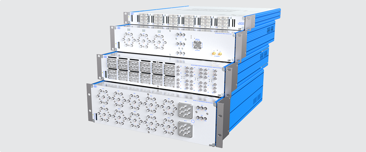
Figure 2 – Above, the LXI form factor can accommodate more payloads and makes better use of space. For instance, the second box from the bottom provides 12 SP6T and 12 SPDT RF relays.
Fundamentally, the card-based and box-based solutions provide very similar functionality as they relate to the system design. Both can be ‘configured’ with relay types that meet the exact needs of an application. The Application Programming Interface (API) provided for each is very similar. In either case, a variety of connectors and cables will be required to benefit from the flexibility the form factors provide. However, as previously mentioned this could potentially result in unacceptable performance hits.
Flexible LXI solutions are ideal for scenarios requiring adaptability and high performance. MSDT accelerates the flexible design process by providing a streamlined approach to developing systems that meet specific requirements while maintaining exceptional performance standards.
How The Microwave Switch Design Tool Enhances Flexible Solutions:
- Streamlined Design Process: MSDT simplifies the creation of switch systems by offering pre-configured templates and design recommendations tailored to RF & Microwave applications.
- Adaptability: The tool allows engineers to design systems that can be easily reconfigured to accommodate changing test requirements, ensuring long-term usability.
- Performance Optimization: MSDT ensures that the designed systems minimize signal degradation, optimize signal paths, and meet space and performance constraints without compromising flexibility.
- Digital Modeling: MSDT provides electrical design and simulation capabilities for both the LXI-based platforms (as in the build example above) and our PXI-based platform. It also enables users to generate 2D drawings and customize front panel relay layouts, helping align electrical design with mechanical constraints.
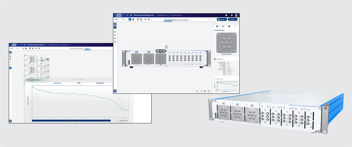
Figure 3 – Above, example MSDT screens for a flexible LXI microwave switching solution and the corresponding unit.
Build 3 –Turnkey LXI Switch & Signal Routing Subsystems
Turnkey systems tend to be considered when performance is of paramount importance and the ATE switching subsystem can be defined in a static configuration with little need for reconfigurability. In these cases, test systems engineers often work closely with their product team to understand the requirements and architect a signal routing subsystem that is designed to deliver optimal performance. Once the switching subsystem layout and basic requirements have been defined, the decision must be made to complete the build in-house or work with a 3rd party to deliver the finished goods.
Best Use of Resources?
When debating in-house vs. outsourcing a project, multiple factors should be considered. In terms of what consumes engineers’ time, there is typically a learning curve to contend with. Which switches are needed? What are their lead times? How are the RF interconnects between modules best made?
The design and build of a one-off ATE can clearly take time, and as the pressure is on to have the system in use and the engineers returning to their other duties ASAP, it is only a minimal amount of documentation (bill of materials, schematics, test plans, etc.) that will be created. Obsolescence mitigation planning may also be sacrificed in order to meet aggressive schedules. Accordingly, at a later date, if an identical ATE is to be constructed to meet an increase in production, the lack of detailed documentation will be a problem. Also, depending on when the identical ATE needs to be built, it might be that the original designer is no longer with the company, and the in-house / personal knowledge is no longer available.
In many cases, embarking on a second build without the correct level of documentation and experience can be as complex and time-consuming as the first time around.
It may also be the case that the system engineering team is focused on the design of the overall ATE system, or even the design of the product to be tested and there is no resource availability to manufacture the signal routing box internally. If this is the reality, then it becomes more desirable to work with a 3rd party capable of distilling broad objectives and turning them into a finished and fully tested ‘turnkey’ product.
If the decision is made to work with a 3rd party to complete the project, the inclination could be to work with systems integrators who specialize in custom test system manufacturing. Assuming they have some knowledge in constructing RF subsystems, they will certainly be able to build and supply a one-off ATE. However, custom manufacturing houses can present the same risks that reside with in-house build, particularly if it is anticipated that additional units will be needed at some point in the future. A more practical solution is to consider partnering with an established volume manufacturer with a broad range of standard/off-the-shelf RF and microwave ATE products.
Pickering's Turnkey Service
Pickering designs and manufactures high-quality modular signal switching and simulation products in PXI, LXI and other formats. Frequencies range from DC to 110 GHz, and power handling of up to 700 W is available.
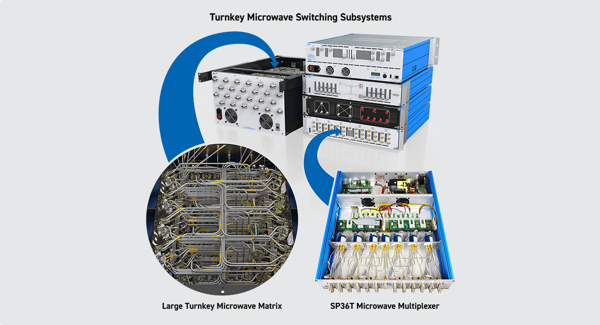
Figure 4 – Above, examples of Pickering’s Turnkey service.
Moreover, the company has a dedicated business unit focused on partnering services and product development. Accordingly, the design and construction of a turnkey, application-specific ATE switching subsystem is managed within Pickering’s systems (including MRP) in the same way as the company’s standard COTS products.
This means a turnkey product is assigned a part number within the MRP system along with version-controlled documents (including schematics and BOMs). Since the turnkey products are based on Pickering’s standard product family, this also means that what is developed will fall under the company’s obsolescence management processes and standard warranty program. Pickering is constantly monitoring for component obsolescence with the objective of keeping products in production for 20+ years. If a second build is required, this is easily accommodated. A strong track record with our suppliers enables us to extend 3-year warranties on the major components used in the solutions that are delivered.
This is therefore a greatly de-risked solution that many of Pickering’s customers are experiencing today. This process has
been streamlined to the level such that timeframes for each distinct project phase are outlined as follows.
Turnkey systems are often chosen for their ability to deliver robust, high-performance solutions with minimal reconfigurability.
MSDT plays a critical role in facilitating rapid development cycles and simplifying complex system integration tasks.
How The Microwave Switch Design Tool Enhances Turnkey Solutions:
- Rapid Development Cycles: MSDT reduces the time required to design and implement turnkey systems by providing automated design tools and pre-validated configurations.
- Simplified Integration: The tool ensures seamless integration of components, reducing the complexity of system assembly and minimizing potential errors.
- Digital Modeling: MSDT is core to Pickering’s turnkey design workflow, enabling a collaborative, model-based approach to custom microwave switch projects. Performance simulation and detailed modeling increase confidence, ensure alignment with requirements, and reduce schedule risk.
- Robust and Reliable Solutions: By leveraging MSDT, engineers can design systems that meet stringent performance and reliability standards, ensuring long-term operational excellence.
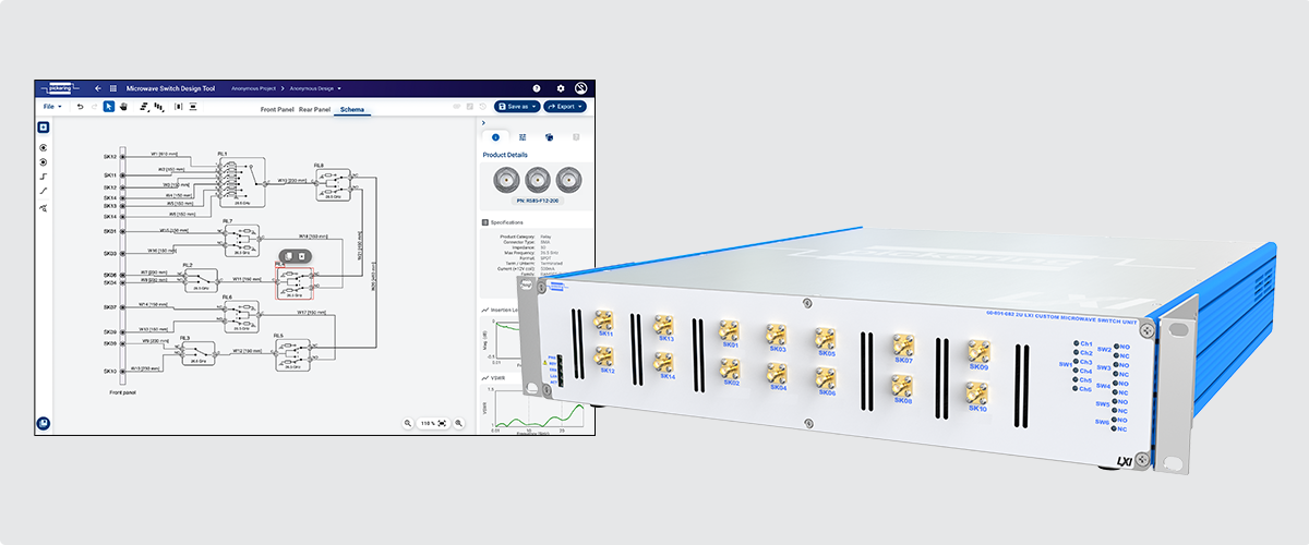
Figure 5 - Above, an example MSDT screen for a turnkey LXI microwave switching solution and the corresponding unit.
Phase 1 – Proposal
This involves discussions with the customer (to really understand the intended application) and finetuning a requirements specification. These discussions include Pickering engineering and project management, and it is often at this point where recommendations are made to enhance manufacturability, performance and maintainability. A proposal will outline the build and include concept models, expected performance parameters, pricing and delivery schedules.
Phase 1 duration: 1-2 weeks
Phase 2 – Project Planning
Once the proposal has been accepted and a purchase order received the component parts needed for the build will be ordered. In this respect, the advantage here – as opposed to a company doing it in-house – is that Pickering is making RF/ MW test equipment all the time and is likely to have many parts held in stock (or available on scheduled orders) plus it has good access to components through trusted suppliers.
Pickering’s project leader (the person who typically prepared the proposal) then briefs the design team as to the project
requirements. Additional documents might be prepared plus there might be further dialogue with the customer to clarify
points.
Phase 2 duration: 1 week
Phase 3 - Design
This phase has three aspects:
- Electrical/Electronic Hardware: This establishes which components and sub-assemblies are needed and how they should connect.
- Software: Suitable drivers are identified.
- Mechanical Design: This primarily concerns the chassis/rack, ergonomics, and cooling.
All aspects are modeled, and calculations (meeting power budgets, for example) are performed. Again, these are all things
Pickering takes in its stride as the company has many standard parts and structures, as well as an extensive library
of software drivers.
Through a close dialogue with the customer and in-progress design reviews changes to the requirements might occur. This
may require returning to the proposal stage.
Phase 3 duration: 2-4 weeks
Phase 4 – Build
Of all phases, this is the one where outsourcing pays real dividends. To build an ATE in-house, a company would need a controller PCB, a means of interfacing with the components and possibly some ancillary boards. This could take up to six weeks per PCB for investigation, design, and manufacture. Pickering, on the other hand, has many standard parts which, if they cannot be used as-is, need only be modified. Also, if LXI is deemed the most suitable form factor, Pickering already has a standardized power supply and controller that provides the Ethernet connection needed to control the instrumentation.
Phase 4 duration: 2 weeks
Phase 5 – Test
All permutations of switch paths are tested to a mutually agreed upon Acceptance Test Procedure (ATP). Characteristics/ results are measured (and supplied in the industry standard S2P format), and a test report is produced. This test report is available for review prior to delivery upon request. Customers can then use the provided S2P files for comparison purposes against their own incoming acceptance tests. Pickering can also provide a retest service for the ATE at a later date, if required.
Phase 5 duration: 2 weeks
Phase 6 – Final
This involves pulling together all the final material, including user manuals, datasheets, and technical drawings, plus of course the test results. The switching subsystem is then delivered.
Phase 6 duration: 2 weeks
The Result
The above phases total 12-14 weeks. As mentioned though, these are approximations based on typical projects and every project is unique. For example, sometimes phase 1 (proposal) takes longer if more documentation is required. Conversely, phase 5 (test) can be as short as a couple of days. Again, it all depends on the complexity of the project.
As mentioned, it may be necessary to take a step or two back, sometimes all the way back to the requirements specification (phase 1), but those steps back would have had to be taken if the ATE were being designed and built in-house or if a systems house were to do the build. Pickering has gained a reputation of being very agile throughout the project build life cycle, operating as an extension to a company’s engineering team.
For this reason, most projects have a degree of contingency built into the advised shipment schedule, where the contingency is available for use throughout any and all phases.
With Pickering, most turnkey projects are turned around within a 12 to 14-week time frame
Also, the above phases are presented in isolation. Once the ATE is complete and delivered, the design will also be added to Pickering’s portfolio as a standard product (with a user manual, datasheet and technical specifications made available for download). This means if the customer needs to order an identical ATE, they can do so easily.
Summary
The design, construction, and verification of an ATE is a drain on engineering resources. The extent of that drain will depend on the complexity of the ATE. Signal routing subsystems in particular are often afterthoughts in a system design even though they are a critical component of a test system.
Companies might be able to take the extremely flexible COTS chassis and module option, in which case it becomes a relatively simple plug and play exercise (particularly using PXI or LXI). They can buy standard products that, where Pickering’s products are concerned, are supplied with datasheets and warranties, and are subject to rigorous obsolescence management.
Or the company may need one or more modified modules - to avoid the performance hit that comes with too much external wiring – in which case Pickering is able to supply these. They are treated as standard parts (i.e., given part numbers, obsolescence management etc.), so if additional units are needed later that is not a problem.
Importantly, Pickering even treats turnkey solutions as standard products and as illustrated above, they can be supplied within 12 to 14 weeks. Here, particularly, the questions business owners and directors of companies making RF or MW products must ask themselves are:
- Could an ATE be designed and built in-house in such a short timeframe?
- Even if it can, how many engineers will we need to divert from their core duties?
- Is it the best use of their time? And, if we were to outsource the build to a systems house that promises a fast turnaround, do they have processes such as obsolescence management in place to give us peace of mind that we could return to them at a later date for an identical system?
Key Outcomes:
- Faster Time-to-Market: MSDT accelerates the design process, enabling quicker deployment of test systems.
- Improved Reliability: Systems designed with MSDT are robust and capable of maintaining high performance over time.
- Scalability: MSDT ensures that test systems can adapt to evolving requirements, supporting long-term business growth.
In summary, partnering with Pickering de-risks any ATE project. Whether the project can be satisfied with standard COTS products, modified COTS products or needs something as complex as a turnkey solution, Pickering can help. The company is platform agnostic and delivers the test capabilities that are of most importance to any OEM or RF and MW products that wants to make efficient use of their in-house resources.


