Contents
22 Jul 2023 • 11 minutes
Secrets to Efficiently Sustaining Your Automated Test System
Cut test system downtime and extend relay life. This white paper reveals proven strategies to sustain automated test systems, plus preventative maintenance techniques engineers and program managers can rely on.
Introduction
When designing an Automated Test System (ATS), it is essential to make a plan and create an efficient maintenance strategy. The reason is simple: an out-of-commission test system means lost revenue for your product line, so a well designed test system and a strategy to get the system up quickly if a problem occurs are vital. In many applications, the lifespan of the ATS is critical because of the long-expected lifecycle of the Device Under Test (DUT). Switching modules are at the heart of modern ATS, providing benefits such as fast test times, accurate and repeatable test results, and minimizing potential operator error. Tactics to consider if you want minimal downtime and a sustainable, expandable test system include selecting vendors that pledge to minimize obsolescence worries, implementing accurate diagnostics to find test system faults quickly, and developing a plan to minimize long repair cycles if and when something goes wrong.
Switching modules are at the heart of modern ATS, providing benefits such as fast test times, accurate and repeatable test results, and minimizing potential operator error.
Relay Types
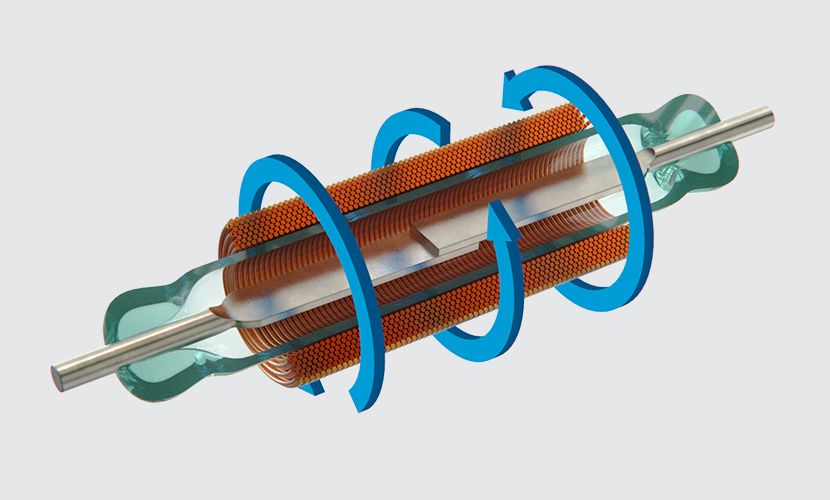
There are two types of mechanical relays: reed relays and electromechanical relays (EMRs). Both have metal contacts that engage when their control lines are energized but there are key differences in their construction. Reed relays have contacts that are hermetically sealed in a glass tube with an inert gas such as argon or nitrogen gas. This is then surrounded by a wound operating coil.
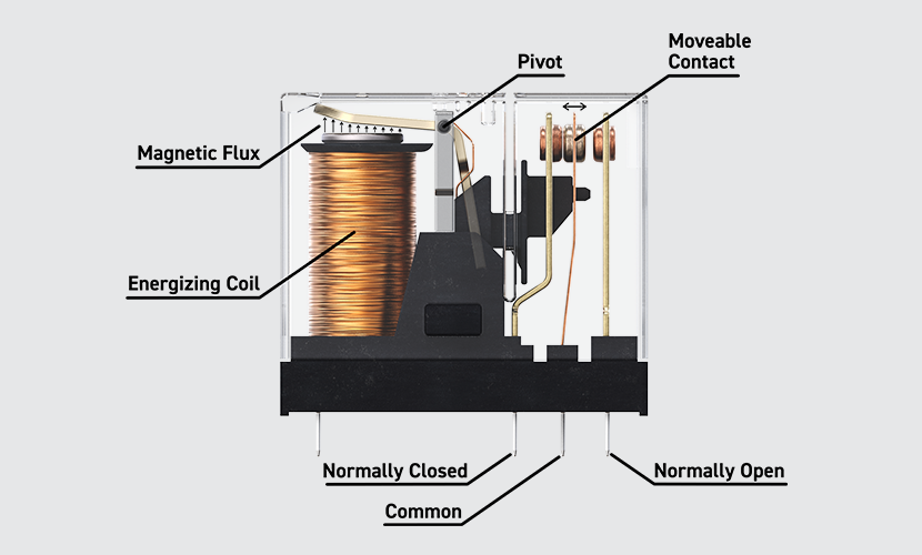
As current flows through the coil, a magnetic force pushes the contacts together, forming the connection path (Figure 1a). Removing the current through the coil separates the contacts. There are few moving parts, which means there are fewer points for failure when compared to electromechanical relays. In electromechanical relays, there are more moving parts (Figure 1b). The EMR contacts are connected to armatures that move on a pivot point connected to a spring. Energizing the operating coil creates a magnetic field that moves the armatures and engages the contacts.
|
|
Figure 1a. Reed Relays |
Figure 1b. Electromechanical Relay |
The manufacturer’s life expectancy specification provides information on when you can expect relays to mechanically wear out. Essentially, this specification is the number of times a relay can operate under specific load conditions. The life expectancy can vary considerably, depending on the load being switched. If the relay is consistently used, switching at just half its rated load capacity, the life expectancy drops. It’s also important to note that operating outside of the specified range will lead to accelerated wear and premature failure.
Determining which relay is best to use depends on the application. EMRs have contacts with larger surface areas, which make them better suited for higher-power switching. They are often enclosed in plastic packages that provide a certain amount of protection from the environment but since they are not hermetically sealed, the contacts over time are exposed to external pollutants, and outgassing from the plastic body can be particularly problematic. All of this can lead to unstable contact resistance, which presents issues for low-level applications.
To facilitate switching at low levels, the contacts are typically plated in gold to resist oxidation. However, when used to hot switch, the gold plating will wear off over time and the contacts become compromised. This is why EMR specifications typically include a minimum switched load specification. Arcing that occurs when switching the load is intended to “wipe” the contacts of any contaminants.
Reed contacts, on the other hand, are hermetically sealed and are less prone to oxidation and contamination, leading to more consistent switching characteristics, and are well-suited for low-level switching applications up to about 2 Amps. With fewer moving pieces, they generally also have longer life expectancies. And because they are hermetically sealed, they have applications in environments such as flight-line test where flammable fumes may be present.
Contact Degradation
How do the contacts get degraded? Figure 2 shows two images of an EMR contact. The left image shows contacts that are pristine, so that when they engage, you can be assured that the contacts will mate completely and carry the maximum current. In the bottom image, those contacts have been used and abused, even if they’re switching rated voltage.
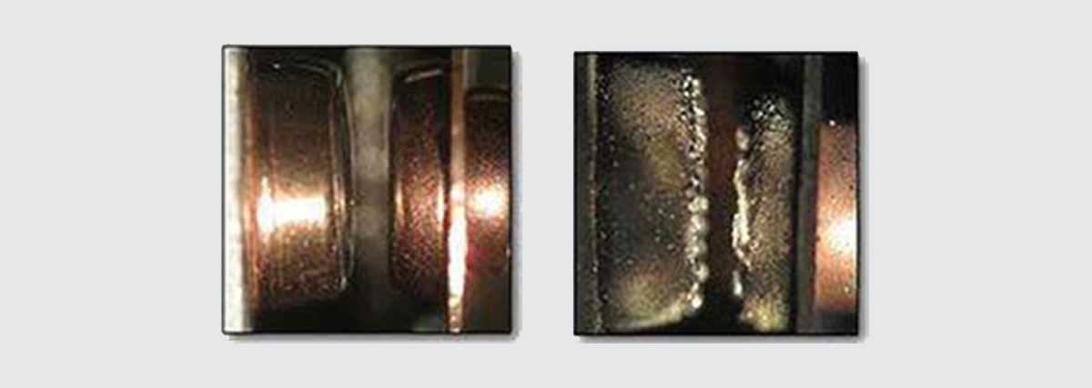
Figure 2. An electromechanical relay contact. (Left) Contacts are pristine when they engage, the contacts will mate completely and carry the maximum current. (Right) The contacts have been used and abused, even if they’re switching rated voltage.
When a relay is either opened or closed while carrying a signal, the relay is “hot switching” the signal. Hot switching is often necessary for a test application but it also results in the most wear and tear on the relay. Relays that hot switch signals are subject to voltage spikes and generally run hotter — conditions that will lead to early life failures. Hot switching at 50% maximum load capacity can reduce relay life by up to three orders of magnitude. In the case of reed relays, typical operating life under light load can be up to 5 billion operations but only 5 million operations at a heavy load.
There is arcing that occurs in hot switching that produces pitting in the contact. The metal turns molten, then shifts, resulting in pitting. The right image in Figure 2 shows that pitting prevents the contacts from mating fully, resulting in inconsistent contact resistance.
It is not always obvious how much voltage or current a relay is hot switching; for example, if a relay is connecting a low-impedance source to a high-impedance load, you would expect the switched current to be relatively low. However, if the cabling or load has significant parasitic capacitance, there may be a high-surge current through the relay when it closes as the source charges the capacitor.
Cold switching is opening or closing the switch when there is no load. Latent voltages could be in the system, especially when there are long cables connecting the switch to the DUT. For this reason, some cable test systems provide a way to discharge any residual charge on the cable assemblies before actuating the relays. As mentioned earlier, the specifications for switching modules normally only define a maximum hot switch voltage/current/power when the module is connected to a resistive load.
Switch Subsystem Failure Modes
It is important to identify failure modes in order to keep a test system up and running. Figure 3 shows switch subsystem failure modes. The upper left image shows a welded contact caused by exceeding the relay specifications, whether it was a high voltage or high surge current when it was closing. The metal got so hot that it melted, welding the contact shut.
If the cause was excessive current, the printed circuit board to which it’s attached also experienced excessive current and those traces carrying the current to the relay will more than likely be compromised and potentially even blown. This type of failure is usually seen when a system is first integrated, and test coding errors may cause an accidental short-circuit. We don’t usually see welded contacts after a system has been validated and is in the field.
Another failure is faulty relay drive circuitry, which is rare. It is fairly easy to identify if you know that the relay driver operates more than one relay; therefore, if the relay driver is bad, it will usually take down an entire bank of relays. If you have a circuit board or a switch card with multiple relays that are failing, it is possible that the relay driver has failed.
Contacts with variable or intermittent contact resistance occur at no-load or low-current levels because of contamination build-up and erosion of the contact materials. This can also occur when the contacts are pitted by hot switching. Severe erosion of the contacts and build-up of debris could prevent the contacts from closing. In the case of debris on the contacts, this is more of an issue with electromechanical relays as their contacts are exposed to air, whereas reed relays have hermetically sealed contacts. Connectors are another common failure mode, whether they’re damaged or loose. A loose connector could present a problem; a damaged connector could make it look like there is a problem with the switch.
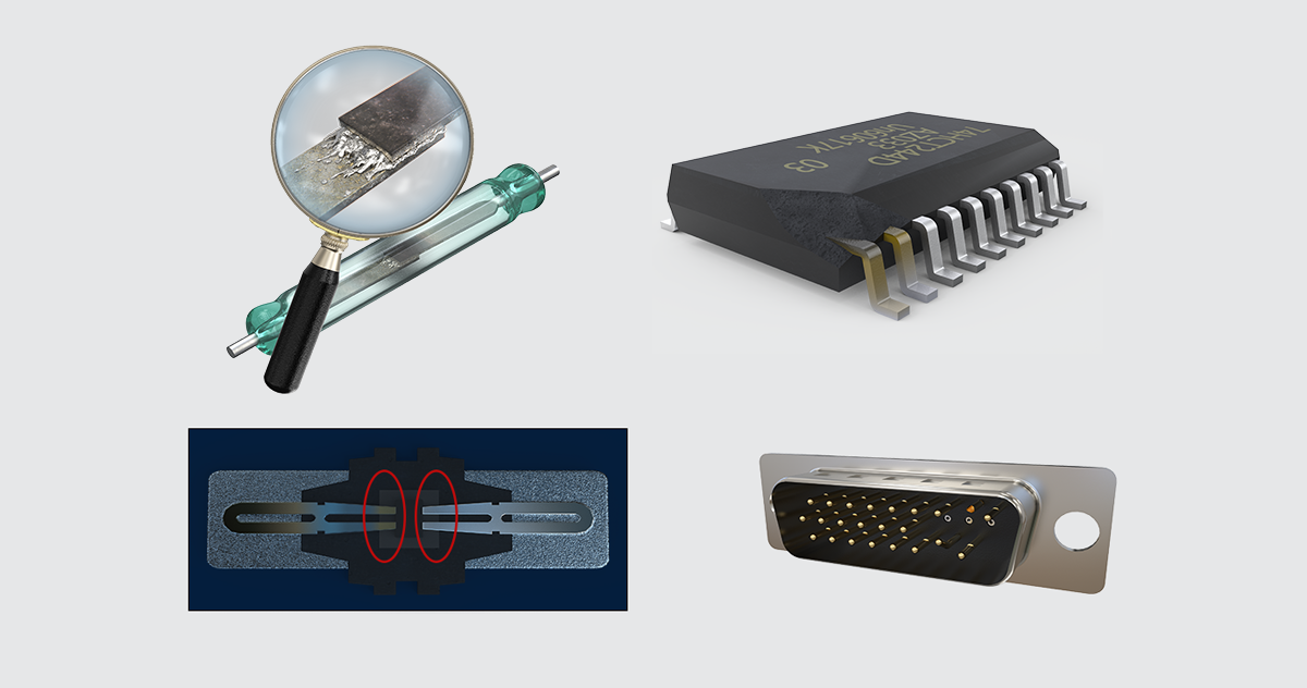
Figure 3. Switch subsystem failure modes. (Clockwise from top left): A failed welded contact caused by exceeding the relay specifications; faulty relay drive circuitry; damaged connectors; and contamination build-up and erosion of the contact materials.
Relay Odometers: End-of-Life Guesswork?
In an ideal world, relays that are compromised can be identified before they fail and shut down production. The easiest indicator that a relay may be reaching its end of life is by the number of times it has been cycled. Once a relay is getting close to its specified maximum operation count, it might be time to replace it. Some switch products offer the ability to count the number of times each relay has been cycled, which is called a relay odometer. This number can then be used as an indicator that a specific relay is nearing end of life and should be replaced.
Production self-tests are designed to get a failed system up and running quickly and usually only isolate a failure to a component in the system that can be easily replaced on the production line — a line-replaceable unit.
Since there can be almost three orders of magnitude variation in life expectancy according to loading factors, it is only advisable to use this method if the operating conditions are consistent across any test article that is connected to the switch. But if the switch is used in multiple test conditions, as is often the case, the user would need to know what the load was for each operation and then have some representative model of how that impacts service life.
Prematurely replacing relays based purely on cycle count can induce more faults through component stress during service (particularly surface-mounted devices) and repeated intervention may render a perfectly good switching system unusable. Therefore, we recommend that production engineers replace relays that have demonstrated failures.
The challenge with waiting for a failure to occur before fixing it is that failures often occur at inopportune times, often in the middle of high production demand. When this occurs, the pressure is on to efficiently diagnose the root cause and return the system to operational status. The most common method of diagnosing a switch failure is the system self-test. This is typically implemented by wrapping system source/measure equipment through system switches to try to identify the failed module.Self-test routines check all components in the signal path, so they will verify not only the switches but also the interconnect system, including a mass interconnect receiver if fitted. Production self-tests are designed to get a failed system up and running quickly and usually only isolate a failure to a component in the system that can be easily replaced on the production line — a line-replaceable unit.
Once a faulty module has been identified, it is usually swapped with a spare known good unit, and the process to generate a PO is started so the faulty unit can be sent back to the manufacturer for repair. The manufacturer will usually use the end-user self-test report to help identify the root cause of the failure for a quick repair.
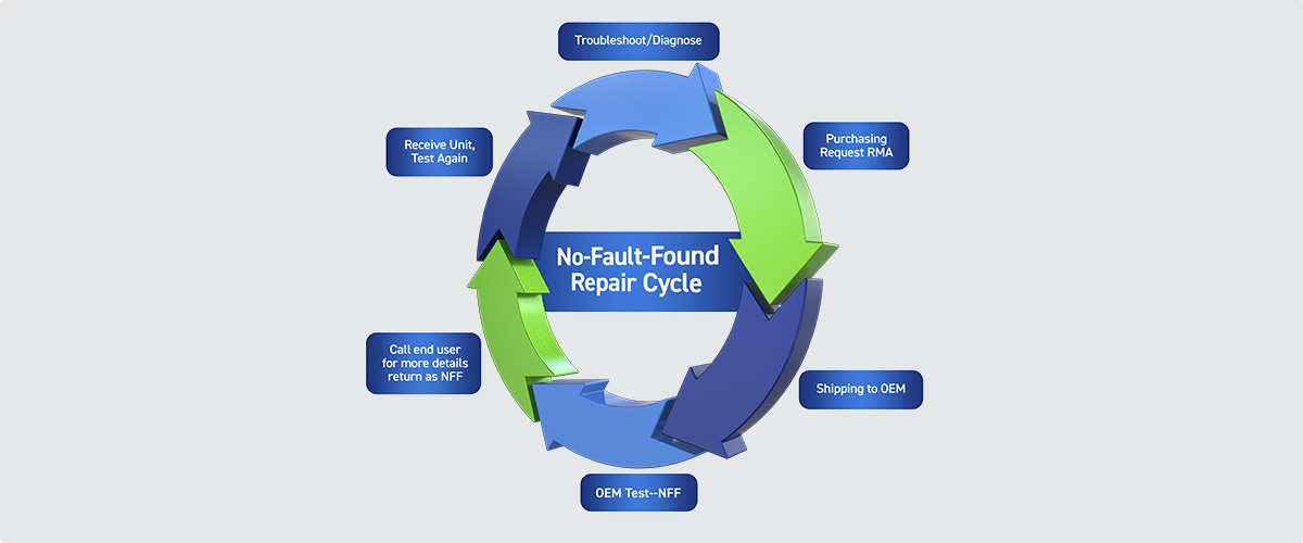
Figure 4. The no-fault-found repair cycle occurs when a good module is returned for repair.
While the test system may be operational and production is up and running again with the known good board, the upstream diagnosis could have created a ripple effect of frustration for others in the organization. For example, the process of swapping modules may have masked the root cause of the failure — possibly a loose cable connection or contact. In this case, a good module is returned for repair and the dreaded ‘no fault found’ cycle will have kicked off (Figure 4). The self-test report may only identify the module as failed with no description of test conditions, which could lead down the no-fault-found path once again. In either case, this is a timeconsuming, frustrating, costly, and overall inefficient exercise for the production team and the switch module manufacturer.
Built-In Relay Self-Test
Many switch system manufacturers are now incorporating self-test utilities into their products to improve fault diagnosis efficiency; however, if your vendor does not provide this capability, you’ll need to budget time and money to build your own. Having said that, even with vendor-supplied diagnostics (such as with Pickering products), you still will need to look at some self-testing capability of your own.
Pickering has developed a product called BIRST (Built-In Relay Self-Test), which is built onto the switch module itself. The embedded resistance measurement unit is controlled by a supplied software application and runs a series of patterns through the module relays. The BIRST software then determines if all the relays are good, questionable, or bad and produces detailed graphical and textual diagnostic information. BIRST is a very quick way to find out what’s going on with a particular board, but can only be used with switch matrices.
On configurations other than matrices — take for example, a switch module with 50 independent relays — there is no easy way to establish a through path between the BIRST source and measure circuitry without adding additional relays to the system. To address these shortcomings, Pickering’s eBIRST Switching System Test Tools provide a much higher diagnostic accuracy and switch module coverage.
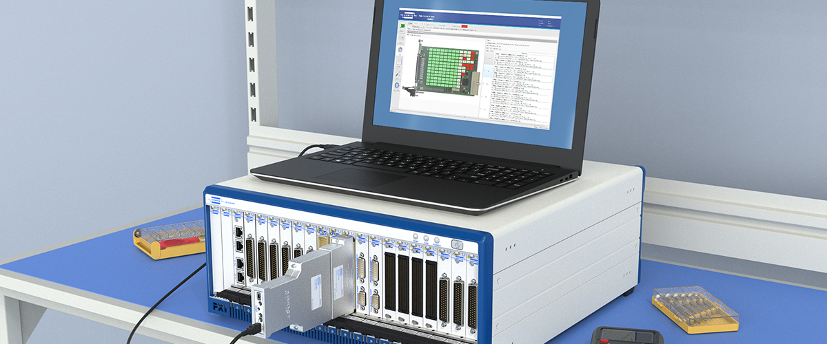
Figure 5. The eBIRST switching system is a combination of source/measure circuitry with a standalone software application. This photo shows the eBIRST tool and adapter plugged into the front of a PXI switch module and connected to the controller PC’s USB port.
Similar to BIRST, eBIRST is a combination of source/measure circuitry with a standalone software application. The major difference is that the source and measure circuitry is provided on an external adapter that is powered through a USB port on the test system controller PC. Each switch module has a specific test definition file that identifies the switch architecture and test sequence (Figure 5).
The BIRST/eBIRST diagnostic test tools are not intended to entirely displace user-developed self-test applications. System-level tools that typically use an external DMM and loop-back mechanisms are useful for identifying a potentially faulty switch module but also can identify cable harness faults. Pickering’s test tools conduct their tests when the UUT and instrumentation are disconnected from the switching system. If they find no faults and a system-level tool does find faults, the problem is likely to be with the interconnection system. The user does not have to create software to diagnose switching faults — only interconnection faults — considerably simplifying the design task for system self-test.
Switching Module
Because eBIRST can accurately measure the contact resistance of all individual relays on a specific switch module, the tool can be used in a preventative maintenance capacity to identify damaged relays that are prematurely reaching end of life before they actually fail. Test data can be collected and trend analysis can then be performed.
In general, for most switching systems, the switch assembly has two principal sources of path resistance: relay contact resistance and connection to the relay from the user connector (often a PCB track; sometimes mainly a wire). The distribution of this resistance is variable from module to module and the total figure is detailed in the switch module specifications as the Initial Path Resistance. It is the maximum allowed resistance of a closed path, usually stated at maximum operating temperature (it generally increases by 0.4% per °C) at the point the switching system is manufactured. We measure every path covered in the data sheet in a cold switch test at an appropriate current for the relay.
As a rough guide, we will typically start to ask questions about a relay if the resistance of its path has increased to twice the Initial Path Resistance. Taking a typical design where 30% of the path is relay resistance, then given the PCB tracks or wires are unlikely to have changed, the relay contact resistance will have increased by almost a factor of six. In some cases, users would agree that this is a reasonable end of life, others might believe that the relay resistance is already too high to be of use in their application, and still others might believe that this resistance is of no consequence as it still causes no measurable signal degradation.
Remember that contact resistance is often not a constant parameter; it can be time-dependent and more importantly, it can be dependent on the signal level applied through it. The resistance might be higher for low signals (for example, measured by a DMM) than for a high current signal. This is particularly true for power relays where the passing of a high current signal tends to burn off contaminants from a contact area while contacts that have not carried high current might exhibit nonlinear resistance behavior after the gold flash on the contacts has eroded. Some relays can be temporarily “cleaned” by applying high signal levels on a hot switch operation, which subsequently improves the path resistance at low currents.
Although relays in paths that have doubled the Initial Path Resistance should be considered nearing end of life, in reality, they may have considerable life left. The only absolute end of life is a failure to open or close — anything else may be application dependent. Whenever we repair switching modules for users, we always check not just the defective relay but the working relays and as a precautionary measure, take the opportunity to change any that we suspect are showing signs of degradation so that an early repeat failure in a different relay is unlikely.
Conclusion
Design of an ATS requires careful planning and must include a system test and sustainment strategy. To ensure that an ATS is fast, accurate, and reliable, the switching portion requires careful selection, as the wrong relay types can fail prematurely or provide inaccurate measurements. A modular architecture provides for quick ATS repair and puts the system back online faster. When possible, maintain a spares inventory of critical switching modules. Finally, a diagnostic plan to verify switching system operation and find defective relays quickly all helps to ensure a long lifecycle for your ATS and assure maximum uptime and short meantime- to-repair (MTTR).