
Contents
13 Oct 2021 • 11 minutes
Using Switch Matrices in Complex Test and Verification Installations
This white paper details how to optimize electronic test systems with programmable switch matrices. It explores matrix types, the challenges of large configurations, and how Pickering's BRIC solutions can simplify complex test setups.
Introduction
A programmable switch matrix is designed to bring automation to an electronic test process by providing an extremely flexible means of connecting test resources to one or more Devices Under Test (DUTs). A switch matrix enables signal routing and signal conditioning to be moved to one central location in the test system rather than it being distributed around various places. The use of switch matrices can save time and cost, reduce test area floor-space and improve reliability. This white paper looks at switch matrices and their use in detail.
Switch matrices are used to automate complex test and verification systems, especially in demanding industries such as aerospace, defense, automotive and semiconductor manufacturing. These matrices help accelerate test times over a manual process for test and facilitate reliable, repeatable and accurate results by eliminating error-prone manual intervention. The use of switch matrices can also help consolidate test processes in a single space, rather than distributing them across several locations. Depending on the matrix type, it can also simplify efforts to add test programs to the test system due to its ‘any test point to any instrument’ capability.
What is a matrix?

|
A switch matrix allows several test resources, e.g., instrumentation and loads, to be flexibly connected to multiple test points on the DUT. The example in Figure 1 shows a 3x3 matrix constructed from 3-way multiplexers. Note: for RF applications, only one device should be connected to any one output, unless the switch includes power dividers. Figure 1. A 3x3 switch matrix constructed from 3-way multiplexers |
1.1. Crosspoint or Tree Matrix
There are two common ways of implementing a matrix, namely Crosspoint and Tree Multiplexer (MUX), and many ways of then using a combination of these methods to achieve the desired switching functionality. Often it is not clear whether a matrix has been implemented using tree MUXs or by a crosspoint arrangement since the functional diagram used almost invariably shows a crosspoint drawing to simply describe the functionality of the matrix. The software driver supplied with the product also hides the complexity of the hardware from the user to make it easier to program.
| fldfjlk |
1.2. Crosspoint Switch
|
Crosspoint switches are arranged in rows and columns and a relay (1 or 2 pole depending on the configuration) is located wherever a crosspoint occurs, allowing a specific row and column to be connected, hence the name. The size of the array is commonly referred to as X by Y, where X is the number of columns and Y is the number of rows. There is, in theory, no limit to the number of connections a particular row or column may have, but if more than one connection is made, the load on the signal source increases. |

Figure 2. Crosspoint switch |
Crosspoint switches are also often described as (or are part of) matrix switches. This is especially true in applications where rows and columns are intended to have only one connection point. As shown in Figure 2, a crosspoint 1-pole matrix uses an array of tracks to connect the Y-axis to the X-axis through a set of SPST relays at each intersection. This is a simple arrangement to understand and is relatively easy to layout; it also gives great flexibility in what connections are permitted.
However, for high-frequency applications, it may be unsuitable because of the bandwidth restrictions it places on the matrix.
In the above example, if Y1 is connected by the relay to X1, then the red track is a stub (an unterminated transmission line). At low frequencies, the stub will add capacitance to the connection so will tend to restrict the highest frequency that can be used without introducing excessive loss. The track also forms a transmission line. When the transmission line is a quarter of a wavelength long, the open circuit at the far end is transformed to a short circuit at the connecting relay - effectively causing a very high path loss in the matrix.The length of the added stubs depends on which path is selected, for example, a path Y1 to X4 has no excess track on the functional drawing so does not suffer from this effect. However, even this path is not free of defects since the relays at each intersection introduce parasitic capacitance (or short stubs) again causing a loss in signal level. The loss may also be dependent on what is connected to those other relay connections.
Other paths will have more than one stub connection, for example, Y2 to X2 clearly has track stubs on both the Y and the X tracks. On large matrices, these can be very long.
PCB tracking also typically does not get designed as a transmission line with a specific impedance on crosspoint matrices. Instead, the tracks are designed around the carry current and the voltage rating of the switching system. Typical crosspoint matrices tend to have rather a low transmission line impedance because of the dense tracking used - PCB layer count can be high and therefore each layer quite thin.
The layout also may not follow the simple arrangement shown on the functional diagram; for example, the path Y1 to X4 may not be the furthest point in the tracking.
|
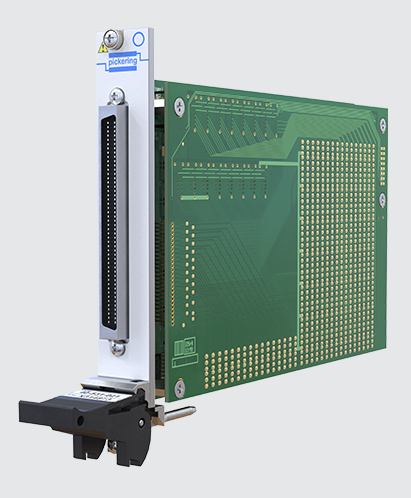
Crosspoint switches of this type are ideal for low-frequency applications where the bandwidth is not critical. It is a very cost-effective solution with few user restrictions. For example, it offers complete freedom on making X to X connections or Y to Y connections as well as X to Y. It is well suited to applications where a connection from X to X is used to connect the instrumentation to the DUT. Figure 3. A 40-531-021 Ultra Highdensity Reed Relay Matrix with 256 Crosspoints |
1.3. Tree MUX (Matrix)
|
Where bandwidth is important, a different construction is required based on the use of a Tree MUX arrangement - see Figure 4. The matrix is formed by connecting a bank of Y input MUXs to a bank of X input MUXs. For a 4x4 matrix, some 16 connections are required to be connected, and many of these paths cross. The number of necessary connections grows rapidly as the matrix size increases. The Tree MUX is optimized for bandwidth; it introduces no open circuit track lengths, and it has few relays connected to any particular path. However, it clearly adds additional costs since the relay count is higher, and the MUX interconnection system may require many point-to-point connections that are expensive or difficult to implement and lead to much lower density designs. |

Figure 4. Tree matrix |
As well as adding cost a matrix using Tree MUXs introduces another constraint - the inability to provide an X to X or a Y to Y connection. Since the Tree MUX selects either one path or another, it cannot connect its common to two tracks, and this prevents an X to X or Y to Y connection from being used. It also prevents two signals from being applied to the same connection on the matrix (hence an alternate term Blocking Matrix). The matrix is inherently designed for Y to X (or X to Y) operation, and the software driver will return an error when attempting to make an invalid connection.
2. Matrix Sub-Types
2.1. Blocking and Non-Blocking
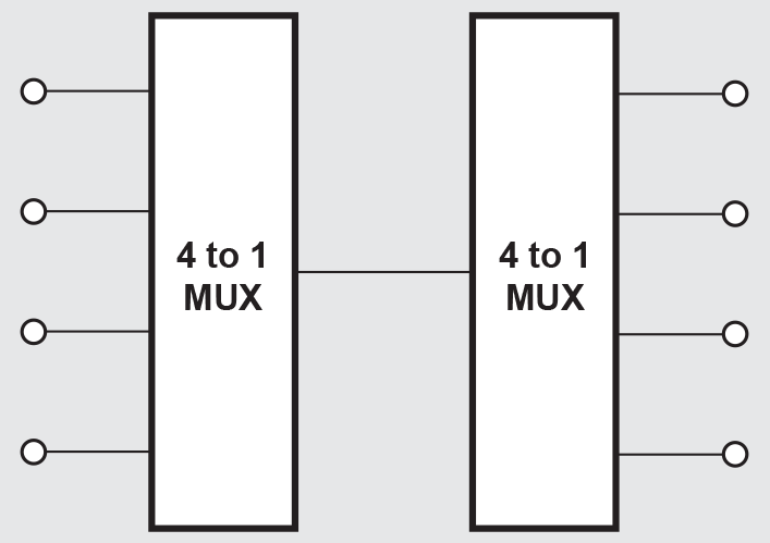
Figure 5. A blocking or sparse 4x4 matrix allows only one connected path |
As above, some types of matrix switches are configured as a blocking switch in order to reduce complexity. The example in Figure 5 shows a matrix where only one device at the input can be connected to one device at the output. All other inputs and outputs are disabled. Some manufacturers also refer to a blocking matrix as a ‘sparse’ matrix. Matrix switches with no blocking limitations may become densely populated with relays as the number of switches will increase in proportion to the number of X & Y connections allowed. For applications where the flexibility of a nonblocking architecture is not required, the simpler blocking matrix may offer better performance and lower cost because of the lower switch numbers. The blocking matrix will, however, impose restrictions on future test applications. |
2.2. Analog Buses and Dual Bus Matrices
The Y-axis rows of a matrix can be considered as a single multi-channel analog bus which can connect to all X-axis columns. In some matrix designs, the test engineer can create multiple matrices programmatically by ’separating‘ the matrix into two or more smaller matrices. In this configuration, relays are added in the Y-axis such that multiple multi-channel Y-axis buses may be connected, each one accessing a section of the matrix’s cross points. The advantage is that the matrix is more flexible in that it can be configured in several different ways as may be needed by the test program for a particular DUT. It may also reduce the size of the test system by eliminating the need for a second matrix. In the example in Figure 6, you see a switching system that may be flexibly configured into one or two separate matrices.

Figure 6. Dual bus matrices
These ‘Isolation Relays’ built into some matrices are automatically used to disconnect the excess stub lengths of large matrices, thus improving performance within any sub-matrix. Pay particular attention to see if this feature is included in your matrix selection if higher frequencies (greater than 5 MHz) need to be accommodated.
|
When differential signals need to be measured or sourced through a switch matrix, two-pole matrices are recommended. For this configuration, DPST relays are used instead of SPST relays, and the differential signals are ‘paired’ to ensure that impedance is matched through the entire path of the switch module. Two-pole matrices are also useful when switching a voltage source using remote sense lines. In this application - figure 7, force and sense lines are switched in pairs to compensate for any voltage drop that occurs along the transmission path. The two-pole arrangement ensures that the sense connection follows the power connection. |

Figure 7. 2-pole crosspoint matrix |
Another way to implement a two-pole matrix is to construct a matrix with double the number of Y-axis rows that are needed and program two rows simultaneously. This is a much more expensive implementation because you will be effectively doubling the number of relays necessary for a test. It can also increase the number of chassis slots required in a modular platform.
2.3. Microwave Matrices
RF and Microwave applications are particularly sensitive to the side effects that a crosspoint matrix introduces as it relates to reflections caused by unterminated stubs and overall system bandwidth. Therefore, microwave matrices are built using a Tree MUX matrix architecture (Blocking Matrix), to isolate a connected path from any residual stubs.
3. Configuring a Large Matrix
When an application requires a matrix with a crosspoint count that exceeds what is available on any individual switching module, a larger matrix can be constructed by externally wiring the Y-axes of multiple matrices together - see figure 8. However, this can cause application coding issues since each matrix is programmed individually, making it challenging to manage the path of a signal across multiple switch modules. Software packages like Pickering’s signal routing software, Switch Path Manager (SPM), can simplify this programming effort by making all external connections transparent to the application software. SPM allows a switch system to be defined by its endpoints (at the test instruments and DUT) so connection paths in application code can be quickly established. It further allows the exclusion of ‘undesirable’ paths such as connections from power to ground.
In addition to programming complexity, larger systems may also suffer from loss of signal integrity due to the external interconnections. The additional wiring adds to the ‘Stub length’ challenge discussed earlier. Essentially, the wiring acts as an antenna and radiates the signal, especially at higher frequencies. Finally, the resultant system will inevitably be higher cost since each matrix module has a redundant communications interface and associated interconnecting cable.

Figure 8. An expansion diagram with four modules interconnected as a 110x16 matrix showing the interconnection challenge
3.1. The BRIC™ Matrix Solution
The Pickering BRIC family comprises a range of over 200 high-density scalable PXI switching matrices. Each BRIC uses a modular construction based on a backplane incorporating a high-performance screened Y-axis bus which has a set of BRIC matrix daughter cards that can be plugged into it. The backplane and the daughter cards are mounted in a metal enclosure 2, 4 or 8 PXI-slots wide which provides mechanical strength and rigidity.
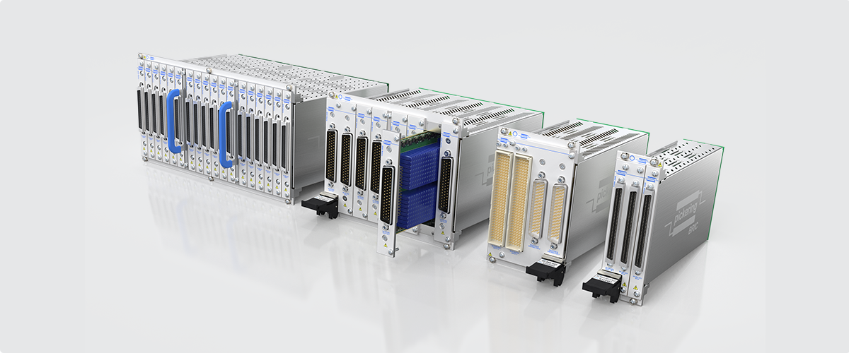
Figure 9. Pickering’s huge range of large matrix BRIC solutions
Each BRIC unit comes configured as a complete large matrix, so internal signal connection lengths are minimized. Also, most BRIC daughter-cards have automatic isolation relays that disconnect them from the backplane Y-axis bus when they are not being used for specific test system connections. These features help to improve bandwidth and signal integrity.
Also, a BRIC is one large integrated matrix with one communications interface to the PC and is therefore much simpler to program than separate interconnected matrix modules.
4. Maintenance of Switching Systems
Switching systems are often placed in vulnerable positions in a test system and are in the critical path between the test instrumentation and the DUT. Also, they are usually required to be operated many times during a test and hot switching of the loads, which adversely impacts the life expectancy of the relay over time. In addition, faults in the DUT may cause unexpected switching conditions (voltage or current) to occur that further limit the relay life. During test system creation, software errors or wiring problems may result in fault conditions that exceed the switch ratings. Considering that mechanical life is sadly always finite, it becomes apparent that switching must be integrated with the expectation that relays may fail. In turn, this means that the product has to be maintainable.
Maintenance Checklist
If a failure does occur, the application often requires the failure to be fixed quickly because downtime in the system costs money. It is therefore essential that the system is designed to allow repair to be carried out at, or close to, the point of use. Several considerations need to be checked:
- Does the product manual identify the relay types used?
- Does the supplier provide a fast way of obtaining replacements?
- Does the product have spare relays installed that can be used to replace defective ones (remember to replace the spares though)
- Does the manual provide a cross-check from the functional position of a relay to its physical position in the product?
- For complex products where fault diagnosis may be complicated, is there a tool to help locate the defective relay?
- Having identified the faulty relay, can it be extracted and replaced without the use of complex tools or having to send it back to the supplier?

Figure 10. A matrix diagram with an example BIRST soft panel |
Pickering Interfaces takes all these aspects into account when designing its switch modules. Every product manual provides all the repair information that is needed and Pickering can supply replacement relays from its stocks. Where feasible, modules do have spare relays fitted, and repairs can be made on-site or at a repair depot. Many Pickering matrix modules also feature integrated Built-in Relay Self-Test or BIRST. BIRST is specialized hardware fitted to the module which, when accessed via a software application, can quickly measure the contact resistance of every relay in the matrix and identify any failures. |
Conclusion
Matrices are a flexible solution that should be part of your test strategy. Depending on the configuration, they allow all instrumentation to access all test points in a DUT(s). Programming can be complex, but software packages like Pickering’s Switch Path Manager can significantly simplify their implementation. There are limitations on simultaneous multipoint access as well as bandwidth. But proper matrix selection can shrink your test system and make it more flexible for today and into the future.


