
Contents
13 Apr 2024 • 11 minutes
The 800V EV Transition: HIL Simulation's Crucial Role
This white paper examines the shift to 800V EV architectures, key testing challenges, and the role of HIL simulation. It also outlines how to build an efficient HILS platform and provides a clear migration path from 400V to 800V systems.
Introduction:
To date, most EVs on the road have 400V power system architectures. However, 800V is shaping up to be the next power architecture of choice, and several manufacturers have already launched models. The move is far from as simple as using higher voltage batteries, though, as all components handling 800V must be suitably rated and be more durable than their 400V counterparts. Moreover, to provide improved reliability and safety features, the 400V architecture cannot simply be reused.
Thankfully, provided it can handle the higher voltages, most of the test equipment used for 400V EV system development and architecture exploration can be reused for 800V, and if the equipment is based on a standard like PXI or LXI, an easy migration path exists if it needs to be taken. This means those developing EVs can make the transition from 400 to 800V without necessarily having to invest in too much (if any) new equipment.
Why 800V?
Most EVs on the road today use 400V architectures, in which the battery packs range from 300 to 500V, providing a balance between efficiency, cost, and performance. However, as EVs become increasingly popular (global sales are expected to jump from 13.8 million EVs in 2023 to 17.8 million in 2024, according to the International Energy Agency), user expectations are rising. Among them, there is a desire for a wider range and reduced charging times.
Both expectations can be met by switching to an 800V architecture – within which battery pack voltages range from 600 to 900V – and some manufacturers, including Porsche, Hyundai, Kia, and Audi, have already launched models.
The advantages of doubling the voltage in an EV architecture are as follows:
- Increased electrical efficiency. This is largely due to:
- Reduced electrical losses. As P = V x I, doubling the voltage means the current can be halved for the same power. However, power loss (which mainly manifests itself as heat) is proportional to the square of current (Ploss = I2R). Halving the current means power loss reduces to one-quarter of what it was before.
- Weight reductions. Thanks to improved electrical efficiency, the size and, therefore, the weight of electromechanical components such as motors can be reduced while maintaining the same mechanical power. Wire gauges (the cross-sectional area, CSA) can be reduced too, now that the current (flow) is less.
- Better range. This is largely due to the weight savings realized from better electrical efficiency.
- Faster charging. As a rule of thumb, the 10 to 80 % charging time can be halved when switching to an 800 V architecture. However, developments in battery cooling are likely to result in even shorter charge times. Note: vehicle acceleration can be improved as well, since the problem to be avoided during rapid charge or discharge is heat buildup; it shortens the battery's life and, if done too quickly, can result in a fire.
Combining all of the above makes for fast-charging vehicles with a long range and, if desired, fast acceleration (at the cost of the range). For example, the recently announced Lotus Emaya – which boasts a 0 to 100 km/h acceleration of less than 2.8 seconds and a WLTP range of 610 km – can charge at 350 kW, which Lotus claims enables a 10 to 80 % charge in less than 18 minutes.
Note: reducing power losses is also behind another change taking place in the world of automotive power - the switch from 12 to 48V. 12V has been the de facto DC voltage in cars since the 1960s, used for headlights, indicators, cabin lights, infotainment systems, etc., and subsystems such as power steering, active suspension, power windows, and heated screens and seats are particularly power-hungry. Again, greater efficiency can be achieved with a higher voltage. This time, quadrupling the voltage means the current can be quartered, and losses reduced to just one sixteenth. A few mild-hybrid vehicles are already using 48VDC, and Tesla’s CyberTruck is the first BEV to use it.
Regarding battery chemistry, lithium-ion (Li-ion) cells, which have liquid electrolytes, are currently used in EV battery packs. An alternative is solid-state batteries. Lithium is still required, but for the same cell energy density, in lower quantities and because the electrolyte is not a liquid, the risk of fire is reduced. Charging is quick too, noting here that many EV manufacturers talk in terms of ‘time to 80% charge’, the reason being that the final 20% of charge can take a long time. Indeed, as cells degrade, they may never accept that final 20% - and the inability to accept more than 80% charge is considered end-of-life for a Li-ion cell in the automotive sector. Indeed, solid-state is a serious contender as a Li-ion replacement, and in 2023, Toyota announced plans to mass-produce solid-state cells for EVs by 2027. Sodium-ion batteries are another alternative battery technology. Though not as developed at this stage, forecasts indicate that sodium-ion cells will account for 6% of the global EV market by 2033.
Challenges of Moving to 800V
Though the move to 800V is seen as an evolutionary step, it is not without its challenges. For example, battery packs will require more subcomponents (e.g., cells) to be placed in series. This could impact manufacturing techniques, for example, making it easier to connect cells in parallel.
The battery management system (BMS) in an 800V EV will need to be more complex than in a 400V one, as it will need to perform voltage, current and power measurements at higher voltages, and the sensitivity (accuracy and resolution) of those measurements will need to be high if defects/faults are to be detected at the earliest opportunity. Indeed, fault detection is more important than ever before, and the BMS and other systems handling high power must be able to initiate a safe and rapid shutdown if required.
Further mitigation against failure is redundancy, which the BMS may also have to manage. Redundancy is a common practice in the aerospace and other safety-critical industries and sees the duplication of some components and, in some cases, alternate routes for power. Some of the weight savings discussed earlier may need to be offset against redundancy measures.
At 800V, there is a greater risk of arcing and insulation breakdown, potentially compromising vehicle reliability and safety. Accordingly, more durable components with higher standoff voltages will be needed. Better insulation materials will be needed, too, and any modules or subsystems that connect to both high-voltage sources/loads and lower circuitry will need excellent, fail-safe isolation.
Also, operating at higher voltages can increase the potential for electromagnetic interference (EMI) within the inverters. This EMI might result in failures if low-level signals are corrupted. Accordingly, enhanced EMC design considerations are needed to prevent interference and to comply with regulatory standards.
There is also the bigger picture to consider, namely EV charging infrastructure and ensuring compatibility with 400V and 800V fast charging. The rollout of 400V charging stations has not been as rapid as EV drivers would have liked, so upgrading some to 800V at this point is not practical. New charging stations can, of course, be 800V, but what if a 400V EV wants to use it? One solution is to use DC-DC power converters within the EVs (see figure 1).

Figure 1 – Compatibility between 400V/800V EVs and 400/800V charging stations will be best addressed through on-board DC-DC converters.
As mentioned, the move from 400 to 800 V architectures is an evolutionary step, one being taken by EV OEMs and those developing major components, who have already invested in (or are still in the throes of investing in) equipment to address the above challenges.
The Benefits of Hardware-in-the-Loop and Simulation
When developing systems for EVs, most companies adopt a test-driven development strategy that uses Hardware-in-the-Loop (HIL) Simulation, in which hardware simulates components under consideration (or under development) and in real-world conditions. In other words, the hardware under test (e.g., a BMS) interacts with a simulated environment that mimics the real-world operating conditions it will encounter. This can include simulating physical conditions, such as temperature, pressure, and environmental factors, as well as dynamic conditions like motion and vibration, thus enabling engineers to see how a system behaves under conditions that closely resemble those it will encounter in the field.
By subjecting the hardware (and software) under development to simulated real-world conditions, engineers can identify potential issues and weaknesses in the design, components, or control algorithms early in the development process. This is crucial for making design improvements and avoiding costly problems later in the product development lifecycle.
A distinct advantage of simulation, where EV development is concerned, is that harsh and extreme fault conditions – such as rapid discharging and short circuits – can be safely created to evaluate the behavior of the BMS, for example, without having to use (and potentially damage) a real battery pack.
Creating a HIL Platform
While a HIL test platform can be created from scratch, the cost (both monetary and time) of doing so can be prohibitive in the automotive industry. The use of an industry-standard platform is therefore highly recommended. There are two standards to consider: PXI and LXI respectively, based on PCI and Ethernet industry standards.
Both are supported by a large number of global vendors, with many commercial-off-the-shelf products available, and both provide seamless, vendor-independent plug-and-play. Of great benefit is that product longevity is assured, and the vendors have obsolescence management processes in place.
A few words on each of the standards:
- PXI (PCI eXtensions for Instrumentation) defines a rugged, modular platform that is both flexible and scalable for building test systems. The standard also defines triggering and timing at the chassis level to aid in synchronization between different modules within the system. Because it is PCI-based, it is also ideal for real-time systems, due to its deterministic behavior.
- LXI (LAN eXtensions for Instrumentation) has no defined mechanical footprint, making it ideal for both integrated test systems and bench-top equipment alike. Accordingly, physically large, cumbersome, or problematic components can be separated from other parts of the test system. In addition, power and cooling requirements are designed around the intended application of the LXI unit, thereby enabling greater efficiency and more specialized products. Lastly, because it is LAN-based, large test systems can be networked (up to 100 m) over Ethernet with no need for repeaters, and an LXI unit can be controlled from anywhere in the world.
Note: Pickering has developed a hybrid solution based on both standards, namely the LXI chassis, which accepts any of the company’s PXI modules. The result: the modularity of PXI (and access to thousands of modules) in a form factor that can be controlled over Ethernet.
400 to 800 V Testing Migration Path
As mentioned, many OEMs and systems houses serving the automotive sector have already invested in equipment – including HILS systems – for the development and verification of EVs. If they are using PXI or LXI platforms, the good news is that, when moving from a 400 to an 800 V architecture, many of the modules they have already invested in will still be fit for purpose, i.e., a large proportion of the test system can simply be reused.
For those parts that cannot be fit for purpose (this tends to be due to the higher voltage ratings), due to the modularity and scalability of PXI and LXI, they can be easily swapped out for upgraded ones
In the next few sections of this white paper, we discuss several of Pickering's products suitable for use in 800 V architectures.
Battery Cell Simulation
This is essential in EV development. Moreover, it is crucial to simulate at the cell level and not just the pack as a whole. For example, the EV’s BMS needs to be able to see a fully charged pack. Accordingly, to verify the function, it is necessary to simulate individual cells ranging from 3.2 to 3.7 V and stack them to achieve the full stack voltage, which means progressing from a 96-cell series stack at 400 V to a 192-cell stack at 800 V.
Also, the BMS is responsible for cell balancing. This means the test hardware needs to simulate each cell’s charge level at rest and during charging and discharging, and to introduce imbalance.
By simulating cells independently, as long as the cell emulator can handle higher voltages, the same equipment can be used when moving from a 400 to an 800 V architecture by simply adding additional modules (i.e., simulated cells) to the stack.
Figure 2 shows the block diagram of a multi-channel battery simulator module available in PXI (41-752A) and PXIe (43-752A). It comprises several power supply channels (two, four or six per slot), capable of supplying up to 7 V and 300 mA, that are isolated from one another and from system ground. The power supplies on the module can therefore be used to emulate a stack of battery cells. Also, each channel can sink up to 300 mA to emulate a battery under charge. Each channel provides independent power and sense connections, allowing the simulator to sense a remote load and correct for wiring losses.

Figure 2 – Above, a block diagram of the 41/43-752A 6-channel battery simulator module.
Note: Although we cite BMS development as the primary use for battery cell simulation modules, they are essentially voltage sources that can sink current and can be used for many other purposes.
High Voltage Switching
High voltage switching can be used in any application within a test system that needs to connect or disconnect signals, as well as move signals between different points, and can be achieved using one of three switch configurations:
- Uncommitted - for example, single-pole single-throw switches (either normally open or normally closed).
- Matrices, which connect any input to any output.
- Multiplexers (MUXs), which connect a single input to multiple outputs.
Each configuration is available with varying numbers of relays and connections, and switching modules are available that can switch up to several kV. Such modules are ideal for any application requiring switching, including use as isolation switching and breaker simulation
High-voltage switching can be achieved using a number of solutions from Pickering, including over 60 PXI modules and 28 LXI modules. For example, the 40-323-701 (PXI) and 42-323-701 (PXIe) are 14xSPST relay modules suitable for applications requiring high-voltage power switching. They have current-handling capability of up to 0.25 A for cold switching up to 9 kVDC (9 kVAC peak) and up to 7.5 kVDC (7.5 kVAC peak) for hot switching.
RTD Simulation
Temperature must be monitored at many locations in an EV, including within the battery pack (at several points), motors, the power inverter, the charger port and within the cabin. A popular and relatively low-cost transducer type well-suited to the task is the resistance temperature detector (RTD). Its resistance is proportional to temperature, and a common device is the PT100, so called because it is made from platinum and has a resistance of 100 Ω at 0 ºC. There are many other types of RTD, though, and RTDs will have either a positive or a negative temperature coefficient (PTC or NTC, respectively).
The simulation of RTDs makes very good sense, as the alternative is to subject the design under test to a potentially wide range of temperatures (which may require expensive environmental test chambers). PXI-based RTD simulator modules are available from several companies. For example, Pickering has many modules suitable for RTD simulation, including the 40-263 (with 4, 8, 12, 16, 20 and 24 channels) that can simulate a resistance range of 40 to 900 Ω, which equates to a temperature range of -150 to 850 ºC, to a resolution of less than 10 mΩ. Figure 3 shows an example module.
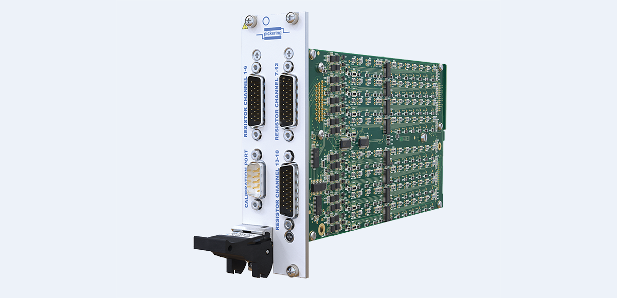
Figure 3 – The 40-263-001 is a 3U PXI RTD module for simulating how the resistance of a PT100 changes over the temperature range -150 to 850 ºC.
To a lesser extent, thermocouples are also used in EVs, primarily during product development, due to their high accuracy. But these too can be simulated, since a thermocouple's output is essentially a small voltage (a few millivolts). Pickering also has a range of PXI millivolt thermocouple simulator modules that provide 8, 16, 24 or 32 channels of highly accurate low-voltage sources. Each channel can be operated over three voltage ranges to simulate any standard thermocouple types in use within the industry.
Fault Insertion/Injection
The ability to insert faults during system development and verification is essential. As mentioned above, systems might need to instigate a safe shutdown or, if redundancy is built in, power re-routed if a fault is detected, and this functionality needs to be fully validated.
Pickering's range of PXI fault insertion units, also known as fault injection switch products, is designed specifically for safety-critical applications where the behavior of a control system, such as a BMS, needs to be fully evaluated under all potential real-world fault conditions.
For example, the 40-592 fault insertion break-out (FIBO) is a large-scale, high-density switching matrix. It is one of a range of modules designed for applications that require simulating a variety of faults in complex designs with a high number of signals/connections, such as a battery pack.
Typical faults that can be simulated include open circuits and short circuits (to another signal/component or to ground), as shown in Figure 4.
Note: In the diagram below, the UUT (unit under test) would be the BMS. Signal X2.1 would normally connect to X2.2. Instead, the link has been broken and, on the BMS side, has been shorted to ground at Y2. Equally, the 284x4 fault matrix could have been used to short-circuit any of the 248 lines to one or more of the remaining 238.
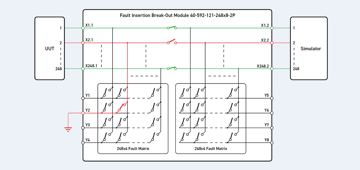
Figure 4 – Fault simulation with a Fault Insertion Break-Out module 40-592-121-248x8-2P.
Summary
There are many benefits, such as higher performance and faster charging, to be derived from moving from 400 to 800 V architectures. However, while using a higher voltage allows for more compact components and smaller-gauge cables/wires – both of which produce weight savings – there is a need for greater durability and safety. There is also an increasing requirement for EV architectures to include redundancy to mitigate against single-point failures and to improve safety and reliability, both of which contribute significantly to the manufacturer’s reputation.
Simulation is the safest way to develop, explore and thoroughly verify an EV’s architecture, systems, and core components. For example, the functionality of a BMS can be verified without using a physical battery pack. Fault injection, such as introducing short circuits, is much safer. Moreover, test conditions and results are easily recorded, which is important for traceability purposes.
The use of PXI- and LXI-based test equipment is a logical choice for manufacturers currently developing products for a 400 V architecture and considering a move to an 800 V architecture, as there is an easy migration path. For example, chassis and controller (in the case of PXI) and modules rated at 1 kV can simply be reused, thus protecting the initial investment.
Doing so enables the optimization of key system components such as the battery pack, motors, power inverters and the BMS. Overall system performance can be determined without waiting for a prototype vehicle to be put on the road. Also, because HIL can be automated, tests can be performed unsupervised, thereby greatly accelerating system development. HIL testing is also highly repeatable.


