
Contents
03 Sep 2021 • 11 minutes
Accelerating Integration in Automated Test Systems
Discover strategies to accelerate integration in automated test systems, overcoming challenges while enhancing design and deployment for optimal test quality throughout the product life cycle.
Introduction - State of the Industry
Defining an automated test system can be challenging: the goal of a test system architect is to accelerate the test system design process, ensure that the system can be easily deployed and sustained throughout the product life cycle and, of course, all while maintaining test quality.
Yet test is often regarded as an expense – albeit a necessary one – and resources may well be directed more toward product design, which will have champions within an organization who can point directly to visible ROI. In comparison, the genuine benefits that a properly architected test system delivers may well be harder to identify (although thorough test practices have proven highly efficient in supporting subsequent litigation over the years). To maximize the productivity of test systems and the process of creating them, it is useful to integrate elements of the test cycle.
This white paper explores the benefits of a well-defined test development process and discusses strategies to accelerate and achieve an optimized, automated test methodology. Pickering’s unique approach to solving challenges associated with signal switching and routing implementations will be presented. Still, many of the thought processes and guidelines can be applied to other aspects of your test system, regardless of the supplier.
The electronics industry is continuously being urged to ‘do more with less, and for less.’ In other words, the pressure is on to achieve greater results using fewer resources and at a reduced cost. This is not a new phenomenon, but it is accelerating as product windows and time-to-profit shrink. Every aspect of a product’s life cycle is under strict cost scrutiny, and this applies particularly to test since the test function cannot be defined as a profit center. In fact, the test function contributes significantly to improving the manufacturing process, product quality and reliability, which positively impact revenue (or, if performed poorly, negatively). Yet mostly, test is seen as a necessary expense which should be minimized if possible.
One of the reasons for this is because test generally has few champions within a company, apart from the test engineers themselves. Product development, marketing, and, of course, sales are far more identifiable as business drivers. In contrast, test can often be seen as introducing a delay in the manufacturing process. To overcome this, the time taken to develop a test process must be as short as possible.
One approach to reducing the time needed to achieve production readiness is to accelerate the integration of automated test systems. This may mean employing a test system integration company that can handle the whole process or using new tools and methodologies directly. There are a number of challenges with either path.
Common Challenges Customers Face
The biggest challenge for most companies is that developing test systems is not their area of expertise. Let’s say, for example, that a customer is a leading innovator in aircraft, electric vehicles or semiconductors. They will want to expend their design efforts on their final product – a new flight control system, ECU or IC. So, although they will require a test system that provides excellent quality assurance, they do not want to spend time designing pieces of that test system. They will look for ways to remove the burden of qualifying the test process.
One way to achieve this is to engage a company that specializes in supplying complete test systems; however, such ‘integrator’ companies often prefer to be guided by the end customer regarding their preferences for test system elements. Also, test system integrators will want to minimize the engineering effort they have to put in since that eats into their margin. In some cases, there may be issues with providing technical data to the integrator due to the competitive or government nature of the product. For both the end customer going it alone and the test systems integrator, the goal is to reduce the number of unique engineering tasks required and to reuse as much as possible.
Repeatability
Test results must be repeatable, especially in a production environment. To enable repeatability, a test system must be stable. Stability can be considered from many angles.
From the standpoint of switching, repeatability means that the test engineer must consider the following:
- Specifications – Are the selected switch modules adequate for the DUT's test parameters? If you are hot switching, will the relays on the switching modules last for an extended period while maintaining consistently low contact resistance?
- Overall Measurement Channel – When dealing with RF and Microwave signals, the overall performance of all components of the channel – switch, cable(s), mass interconnect, etc. – must be added up. Let’s say the DUT can work reliably with a maximum loss of 1.5dB to the test instrumentation. If the switch has a 1dB loss and each cable has a 0.5dB at the test frequency, and there are three cables plus the mass interconnect (instrument to switch, switch to mass interconnect, mass interconnect to DUT), you could unknowingly have over 2dB of losses in the channel and experience inconsistent measurements.
Repeatability also applies to manufacturing. A test system manufacturing process that lacks careful planning or is poorly defined can lead to variation in the quality of the systems being built. These variations can impact the consistency of the test results produced, which can negatively affect the confidence in the quality of the product being shipped.
The bottom line is that if your test engineers lack expertise in these areas, you must ensure that your switching and cabling vendor(s) of choice are knowledgeable and can quickly support your test system design phase. And if this is the case, it may also be useful to consider subsystems from commercial suppliers that integrate technology pieces (e.g., cabling, instrumentation, software) to drive a measure of repeatability into your test system.
Flexibility
Automation, if implemented poorly, can limit the use case of a test system design to a small subset of applications. Thinking ahead to other products that may be supported by this test system will promote the reuse of engineering development effort and reduce costs associated with redundant tasks. Using a modular platform as the foundation for switching requirements allows systems to be easily scaled up or down depending on the complexity of the product being tested. This approach allows systems to be optimally designed for an application in terms of size and cost, with minimal additional engineering effort. In short, introducing a modular architecture into your test system design that can scale as new requirements are introduced is crucial to successfully future-proofing your investment.
For example, to guarantee flexibility in automated switching systems, a large selection of industry-standard format, modular switch products with varying channel counts, and a range of capabilities should be readily available. This will ensure the scalability of the test system to handle product updates and new applications promptly.
Some questions to consider, especially in the area of modular test:
- Does your modular chassis have enough spare slots for future requirements? If not, is there adequate room in the test rack for an additional modular chassis?
- Electrical noise – If you are working with high voltage applications, you may want to keep the switching in a separate chassis, away from sensitive instruments.
Documentation
Products and system elements are manufactured worldwide, so proper documentation is essential for remote support and for replicating test systems. Custom-designed test systems can often suffer from poor documentation, which negatively impacts productivity, repeatability and quality of test results.
Some questions to ask:
- Do the software tools you are using for writing test code create clear, adequate documentation for long-term deployment?
- When you use a service or software tool to design cables, what kind of documentation is provided?
- Does your switching provider supply CAD files of their modules so you can easily create a CAD drawing of the overall test system?
Strategies and Considerations to Accelerate Integration
Test system component suppliers are addressing many of these challenges with new tools or added functionality. These can broadly be categorized as follows:
Simulation and Debug
Test hardware simulation tools can provide users with instant feedback on their application development. Figure 1 shows a Rapid Application Design model, in which all the elements, including design, development, refinement, demonstration, and even testing, can be carried out without real hardware. This saves time when you have not yet received your hardware but want to start developing test code. Simulation will also reduce the risk of accidental hardware damage during the debug phase.
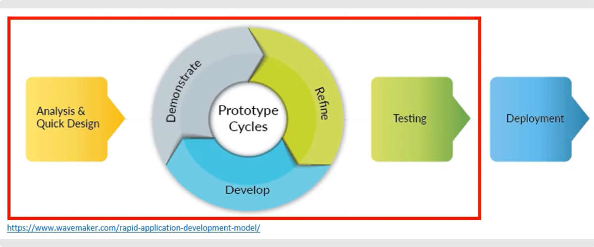
Figure 1.Rapid Application Design Model
Signal Routing
Routing an electrical signal between a test instrument and a DUT (device under test) can require navigating a complex network of interconnected relays, wiring and interfaces. The ATE software engineer must determine the correct position setting of multiple relays to establish the desired route. This can be a time-consuming exercise across multiple pages of a schematic, and the time required to debug any errors can lead to delays in getting a system through integration and into production.
Programming methodologies are now available that ‘map’ this task automatically, enabling test engineers to connect instrumentation to a DUT without needing to decode schematic pages, and allowing the use of intuitive endpoint names for clarity and fast verification. Such tools reduce the time it takes to get the software code through validation and into production readiness. They can also prevent undesirable connections that may damage the test system and will automatically provide full signal routing documentation.
Cable Design
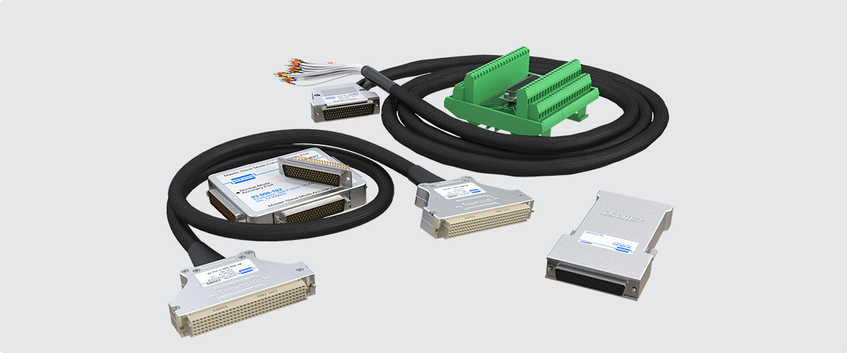
The cable design for a test system is probably the last section of its development. Still, because proper cabling is critical for repeatability and accuracy, it needs care and expertise. Depending on the application, the test engineer needs to consider test specifications, including voltage, current, temperature, insertion losses and more. From there, the engineer needs to determine the connections between the instrument and the DUT, and then select connector types, backshells, wire lengths, and wire types. Unless the test engineer is an expert in cabling, researching wires and connectors can be daunting. Even if that expertise is available, designing the interconnect will be a complex process while checks are made, resulting in a significant investment in time and money, in some cases, even exceeding the initial purchase cost of the test module being connected.
Fortunately, manufacturers are now introducing cabling design tools that automate and document this process.Self-Test
Developing a self-test strategy is a significant effort in an integrated test system. Now manufacturers are starting to offer various self-test functions as part of standard modules that are sold off the shelf.
Industry-Standard Platforms and Products
By selecting standard products that conform to industry standards, test system engineers will avoid many issues that cause integration challenges. First, the system elements will be proven and rugged and should not suffer from interoperability problems. Second, they will be scalable to match the changing needs of the test system. Third, they will come with full documentation.
Other things to consider:
- Is the vendor’s product range more than adequate for your testing needs?
- If the right switch module is unavailable, how easy is it to implement new designs?
- Are the switch modules likely to be available over the life of the test system, which may be 15-20 years or longer?
Pickering Interfaces’ Test Integration Solutions
Pickering is a leading manufacturer of switch modules and other products for automated test systems. The company has developed several unique tools and services to aid system integration and speed test system development. A selection is presented here:
Hardware Simulator
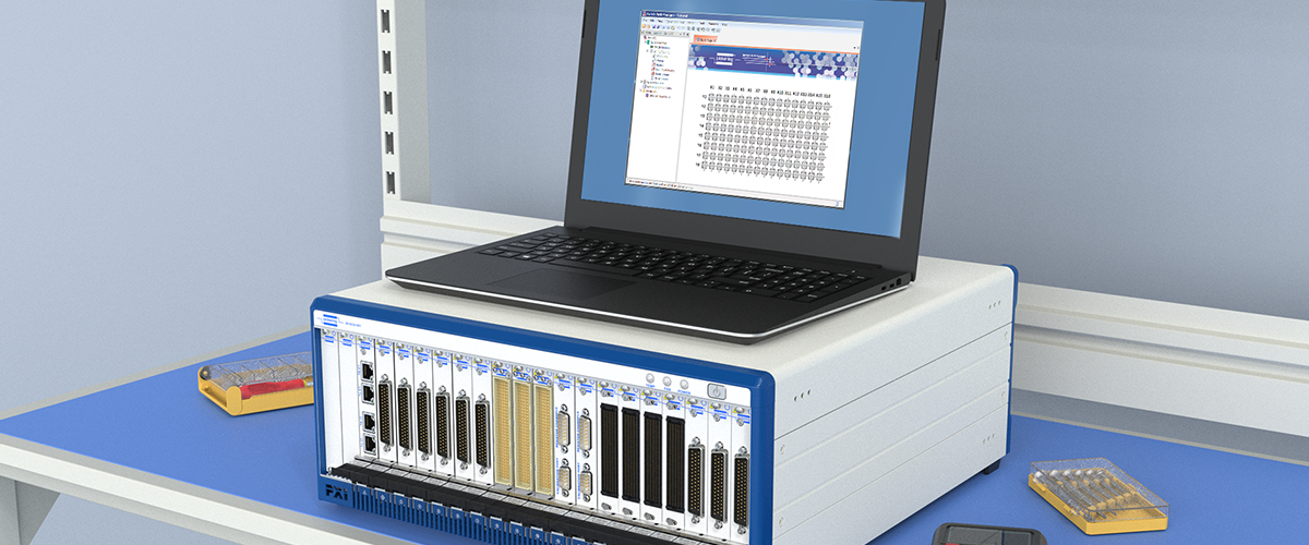
The Simulation Tool, model 60-901-001 (Figure 2), supports over 1000 switching product configurations, enabling the simulation of all Pickering’s PXI and LXI switching products, as well as most of the company’s PXI simulation products. The tool supports each product as a virtual device, allowing code development independently from the application hardware. The tool also has the ability to show real-time switching and debug information and comes complete with a driverless soft front panel that provides complete control of the simulated modules’ functions.
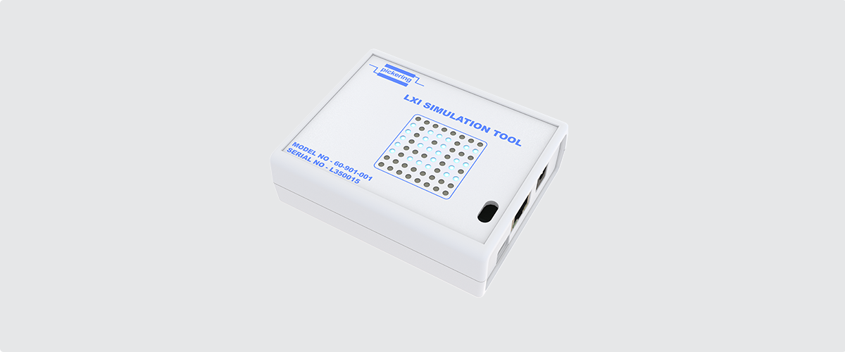
Figure 2. Pickering’s 60-901-001 Simulation Tool
Figure 3 shows the simulation of Pickering’s PXI modules using the Simulation Tool. An 8x8 LED matrix on the tool, along with a web panel, displays the simulated module's switch status for debugging. With this tool, you can code and test a control application before purchasing or connecting to the actual test system, significantly reducing project lead times. The Ethernet interface enables simple control through standard LAN interfaces found on all system PC/host controllers.
With this tool, you can code and test a control application before purchasing or connecting to the actual test system, significantly reducing project lead times.
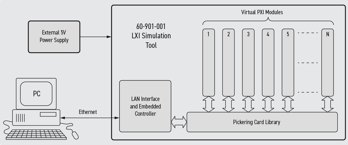
Figure 3. Pickering’s 60-901-001 - Simulation of Virtual PXI Modules
Switch Path Manager
Switch Path Manager (SPM) is Pickering’s interactive signal routing utility that essentially maps a wiring and interconnect schematic into a configuration file that can be used to accelerate and simplify code development (Figure 4). This mapping is a one-time effort in which all external connections between relays and modules, as well as logical, intuitive endpoint names, are defined. This configuration file can then be referenced in application code through the Switch Path Manager API. One line of code can be called to correctly set the position of all relays in the required path.
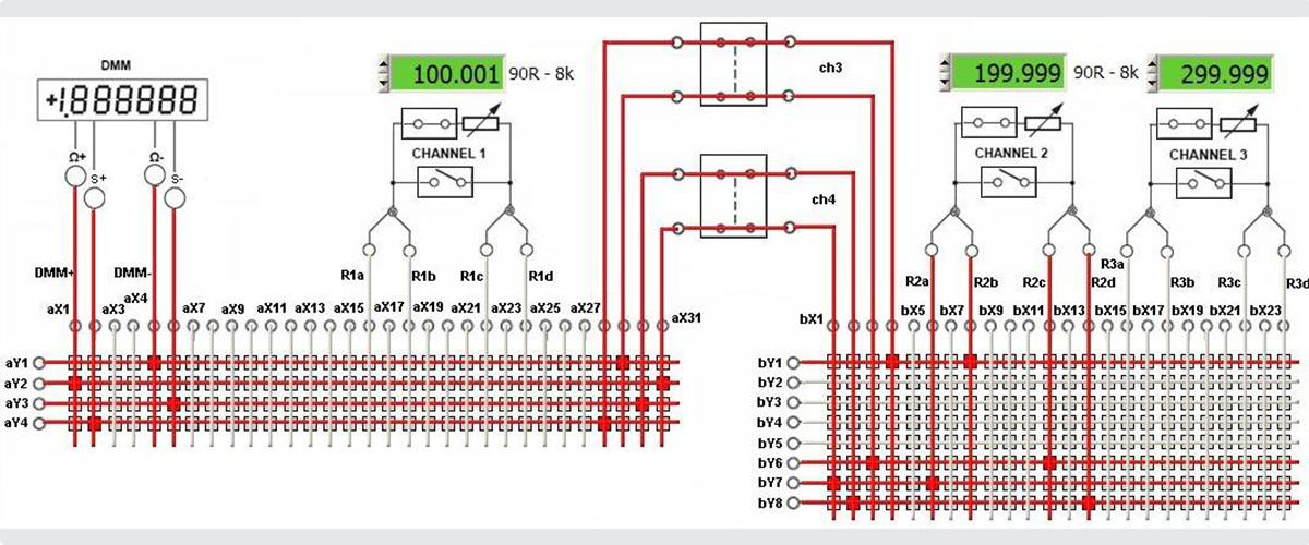
Figure 4. Example of Pickering's Switch Path Manager Utility
 Once the schematic has been mapped in SPM, software engineers responsible for developing application code do not need
to become familiar with the low-level interconnections between components; they can focus entirely on their area
of expertise. Using logical endpoint names in code, rather than generic relay nomenclature, makes it much easier for anyone reviewing it to understand and maintain. Fewer lines of code mean less opportunity for errors that delay production readiness.
Finally, SPM can manage potential routing conflicts, minimizing the likelihood that undesirable route combinations could damage the test system.
Cable Design Tool
Pickering’s free, online Cable Design Tool (Figure 5) lets test engineers graphically create custom cable assemblies from scratch or by using a built-in library of standard cable sets. The tool helps users quickly define and document the cabling required to facilitate a repeatable manufacturing process. When the design is completed, the tool creates a full datasheet with all part numbers, lengths, labeling and pinout map for each path, which can be downloaded in PDF format. Pickering’s technicians can then generate a competitive quote; however, engineers are free to take that document to another provider if preferred.
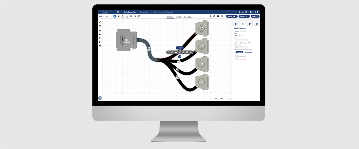
Figure 5. Example of Pickering’s Cable Design Tool
BIRST and eBIRST Diagnostic Test Tools
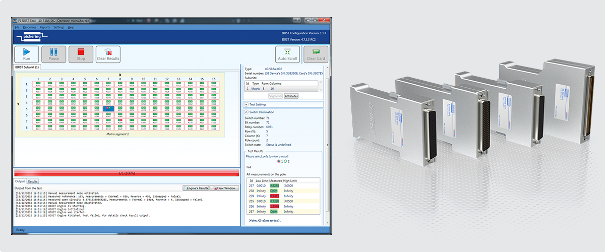 Manufacturers such as Pickering now provide switch matrix solutions that include a built-in self-test facility called
BIRST™ (Built-In Relay Self-Test), which addresses the shortcomings of older self-test systems and relay operation counting
methods. BIRST is implemented as a very compact hardware addition to the switch modules; the source/measure hardware
is on board, and resistance measurements are automatically performed via the matrix relays. The test process is fast, each
relay requiring just a few 10s of milliseconds to fully test. The software then displays the test results as a graphical
representation of the matrix, highlighting faulty relays and allowing the user to quickly identify the physical positions of these components. Spare relays are fitted to most of Pickering’s switch modules, so a faulty relay
may be quickly replaced in the field without voiding the company’s standard 3-year warranty, minimizing repair time and
maximizing test system uptime.
Another switch module self-test development from Pickering is eBIRST™ (external BIRST). eBIRST works similarly to BIRST but requires an external test tool to be connected to the switch module under test. The relay testing source/measure hardware is contained within the tool, and the eBIRST software application exercises both the module and the connected tool, returning relay test results and analysis. This allows the user to analyze the switching system right out to the external interface (including the connector). The advantage of eBIRST is that it is available for any switch-module configuration, not just matrices.
Selector Tool
It is only possible to support test system flexibility, scalability, ruggedness and ease of configuration if your supplier has a broad range of modular switching and simulation products available on industry-standard test platforms. Pickering’s deep portfolio of 1000+ PXI, PCI, LXI & USB products assures that test architects can optimize their system switching to exactly fit their requirements.
The company has an online Product Selector Tool that quickly guides users in identifying the product that most closely matches their requirements by filtering through different specifications and narrowing the options to arrive at a suitable part.
New Designs
Should a standard product not be available to suit a particular requirement, Pickering will consider creating a new product to meet the needs of the application. Once delivered, Pickering will migrate the design to its standard catalog (with the customer’s permission). This means the customer will benefit from comprehensive documentation and product longevity exceeding 15 years.
CAD Models
In order to simplify the generation of high-quality test system documentation, 3D models of all Pickering modules are available to help with debugging and enable test systems to be easily replicated.
Conclusion - Design/Deploy/Sustain
Test Engineers are continually asked to take on more tasks. Test is not a profit center, and precious engineering resources may well be better focused on delivering a world-class end product rather than ‘reinventing the wheel’ by taking on sometimes complex and mundane test system design challenges that have already been addressed by a specialist company.
In some ways, it’s a classic ‘make vs. buy’ discussion—and having a vendor with the necessary expertise will help get the job done, on time and on budget. Pickering delivers the hardware, software tools and expertise you need to quickly define test system switching and cabling and to develop test code. The company has helped customers across multiple application spaces extend their engineering team’s effectiveness by sharing its experience and providing a collaborative, creative and agile approach to the system switching design process. Pickering’s goal is to support its customers through all life phases of a test system, from design and deployment to long-term sustainment.
Many tools are available to help integrate test systems and speed test system development. This white paper has focused on ways to make the integration phase of a test system project more efficient and easier. However, Pickering offers products, support and guidance across a test system’s entire lifetime.


