
Contents
16 Sep 2025 • 14 minutes
Accelerate and De-Risk NextGen Aircraft System Design
Learn systematic, test-driven development methodologies that reduce test cycles, streamline validation for complex integrations, and improve reliability, flexibility and scalability for advanced, mission-critical avionics test projects.
Introduction
Though the development and testing of next-generation aircraft (NGA) technologies are fraught with advanced technological challenges, proven test practices and methodologies still offer great benefits.
This white paper explains the many benefits of using hardware-in-the-loop (HIL) simulation techniques during the development and functional verification of NGA modules and systems. It also details the essential components of HIL systems and underlines how an established industry-standard modular HIL system architecture, such as PXI, can readily keep pace with NGA’s new technology requirements. Specific examples of simulation, switching, and fault insertion solutions are provided.
What is a Next-Generation Aircraft?
Next-generation (NextGen) refers to using the latest technologies to achieve specific goals, including improved performance (range and/or speed), safety, and reduced emissions. The technologies employed include advanced avionics, with increasing levels of automation (leading to fully autonomous solutions in the future) and more advanced flight management, navigation, communication, and (in the defense sector) surveillance, combat, and countermeasure systems.
Improved fuel efficiency, a goal common to commercial and defense aerospace, is achieved through advanced aerodynamics, lighter materials, and enhanced propulsion systems, including hybrid technologies. Greater electrification is also common in both sectors, with electric actuation used instead of hydraulics, for example, and higher voltages used within the aircraft’s power architecture to reduce weight.
Sustainable aviation fuel’s (SAF) use in combustion engines, hydrogen in fuel cells powering electric motors, and hybrid technologies are also key aspects of NextGen, as the aerospace industry faces stricter environmental regulations.
Other key aspects of NextGen are increased modularity (systems that are easier to maintain, upgrade, and reconfigure), sustainability to reduce long-term environmental impacts and the use of rare-earth elements.
Example NextGen programs and technology demonstrators under development include:
- Boom Supersonics’ Overture
- Global Combat Aircraft Program (including Tempest)
- NASA’s Quiet Supersonic Technology (Quesst)
- Next Generation Air Dominance (NGAD)
Brief descriptions of each, including links to websites, can be found in the Appendix of this white paper.
Next Generation Aircraft Engineering Challenges & Solutions
Next-generation aircraft (NGA) have highly integrated modular architectures within which multiple software-defined functions are hosted on shared hardware. Moreover, many of the modules needed for an NGA are complex, real-time embedded systems that rely on information from multiple sensors to make decisions. Indeed, an NGA might have thousands of sensors used to monitor engine performance, environmental conditions, etc., and some data (radar and LiDAR, for instance) needs to be fused in real-time with Global Navigation Satellite System (GNSS) data.
The volume of data that an NGA needs to generate, process, and share is potentially in the tens of TB per flight, and NGA platforms use high-speed comms buses (sometimes multiple) for data transfer. For instance, avionics full duplex switched ethernet (AFDX) is being used for safety-critical systems; noting here that AFDX is a registered trademark of Airbus, but the core technology is in the publicly accessible ARINC 664 standard. Data transfer through AFDX is managed through deterministic scheduling, virtual links (VLs), and bandwidth allocation gaps. Because the AFDX/ARINC 664 is used on safetycritical applications, verifying that the system responds safely in the event of failed data transfers is essential.
In addition, high-speed data links—through satellites and 5G networks—exist with the outside world, as an NGA is essentially a node within a large system. For example, vehicle-to-everything (V2X) communications must occur with air traffic control, ground stations, and other aircraft. Two challenges here are spectrum management and, in the defense sector, the development of anti-jamming technologies.
Also, with NextGen aerospace being so highly integrated, the cyber threat attack surface is significantly increased. Using more advanced data encryption, root-of-trust hardware, and ‘secure software’ development lifecycles can help improve cybersecurity, but it also must be verified.
Alongside these NGA development challenges, there are the traditional engineering challenges of achieving size, weight, power, and cost (SWaP-C) goals: i.e., the need for smaller, lighter components and subsystems, high power with minimal thermal management, reduced costs throughout the entire lifecycle of the product, and achieving more with fewer resources. An additional challenge is increased reliance on supply chains that are too easily disrupted by world events.
The aerospace industry is, of course, heavily regulated, and software must comply with DO-178C and hardware with DO-254 standards; for instance, safety-critical redundancy and fail-safe mechanisms must be demonstrated to work correctly. Due to growing system complexity, certification compliance takes time and is expensive.
Solutions to the above challenges include model-based systems engineering (MBSE), a methodology that uses detailed models (a.k.a. digital twins). The models can be used in augmented reality (AR) and virtual reality (VR) environments to visualize components and subsystems, aiding remote collaboration between engineers in different parts of the world and allowing errors to be detected and corrected ahead of physical prototypes.
What is Hardware-in-the-Loop?
In addition to the above solutions to aid the development of NGA systems, the well-proven technique of hardware-in-the-loop (HIL) simulation is the obvious solution for the design verification of NGA Line-Replaceable Units (LRUs), components of avionics electronic control systems that will contain millions of lines of embedded software—as an example, the Boeing 787 Dreamliner uses approximately 6.5 million lines of code embedded in various processors throughout the aircraft for its avionics and onboard support systems.
HIL simulation allows a system’s real-world environment to be emulated offline in a controlled test environment. This allows safety-critical LRUs to be thoroughly exercised across all possible operating conditions—including fault conditions— to confirm they operate safely and predictably in all situations. HIL simulation is an established and ubiquitous test methodology, and providing the HIL core system architecture is flexible and scalable, existing HIL solutions can be readily adapted to meet the technological challenges of NGA.
A computer-controlled HIL test system provides stimulus to the Device Under Test (DUT) by replicating the outputs and response characteristics of everything the DUT expects to see as inputs, placing emulated loads on the DUT’s outputs, and interfacing with the DUT via its communications channels.
The heart of the HIL environment is a host computer (for test management and execution) paired with a real-time controller (containing environment and system behavior models). There will also be a host of inputs, outputs, and interfaces, as well as break-out boxes (BOBs), as they provide easy access to signals for test and verification purposes (i.e., connecting an oscilloscope) and facilitate manual fault insertion. Figure 1 provides an overview.
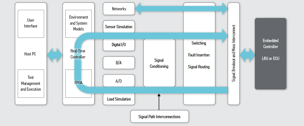
Figure 1 – The architecture of a HIL test system.
The Benefits of HIL Simulation Include:
- Cost Savings. Evaluating design iterations using simulation techniques means fewer prototypes (and physical test rigs) are needed.
- Time (and additional cost) savings are realized by testing earlier in the development cycle because bugs can be identified and fixed before they can migrate further into the design flow.
- Safety (and additional cost) savings. Operating under real-world conditions, such as flying at altitude or under temperature extremes, can be verified without risking damage to equipment or the cost of hiring environmental test chambers.
- Fault injection is the introduction of faults, such as signals lost through open and short circuits, unresponsive hardware (e.g., stuck actuators), and corrupted data (e.g., lost data packages). Note that it is much easier to simulate these faults rather than physically create them. It is safer, too, if the test condition involves high voltages, for example.
- A HIL system can also be used for highly accelerated life testing and stress screening (HALT and HASS, respectively).
In addition to the above benefits, HIL simulation allows the development of the NGA system to be split into separate tasks, which is highly efficient because the sub-teams can work relatively independently. For instance, a sub-team might be focused on developing a software module for engine temperature management. They can connect all the temperature-related hardware to a test bench connected to a computer, which resides in models of engine dynamics, such as turbine and compressor behavior, fuel and airflow, and thermodynamic and mechanical parameters.
A HIL test environment can also switch between simulated and modeled components.
Traceability is key to verifying the NGA module or system, particularly in such a heavily regulated industry. The HIL system software comprises scripted test cases and sequences, and the results of all tests can be recorded. Moreover, many measurements can be taken from emulated loads that cannot easily be taken with real-life loads. Because everything can be recorded, test conditions and procedures can be replicated to verify future upgrades to any given module.
The Advantage of a Modular HIL Architecture for Next Generation Aircraft System/Platform Development
HIL simulation systems are universally employed for ECU design verification in many high-technology industries, including automotive and aerospace. As mentioned, HIL involves emulating everything the DUT will interface with, i.e., sensors, actuators, digital I/O, analog signals, and comms buses. An industry-standard modular HIL system architecture, such as PXI, is exceptionally beneficial to the adaptation and enhancement of an existing aerospace HIL system to handle potential NGA requirements, as it provides unrivalled multi-vendor instrumentation choice, scalability, and flexibility, together with the guaranteed longevity demanded by the aerospace industry.
The following sections will explore how specific sensors/transducers are simulated, how electrical loads can be added to the HIL system, and how faults are simulated—all with a view to accommodating NGA requirements.
Temperature
An NGA will require temperature measurement at hundreds of points. Depending on the temperature range and accuracy required, different sensor types may be used, including thermocouples, resistance temperature detectors (RTD), and thermistors.
PXI modules are readily available that can accurately simulate all of these sensors, ensuring that non-linearities, reference temperatures, and fault conditions are properly represented. This means that if the system under development is a FADEC, it can be validated for normal and extreme thermal conditions without using a real engine.
Thermocouples consist of two different types of metals joined together at one end, creating a junction. When the junction of the two metals is heated or cooled, a voltage is created that can be correlated back to the temperature. Thermocouples are the best choice for working at high temperatures, with some models capable of withstanding 2,500 °C . They are used in aircraft to measure temperature in various systems, including engine components, exhaust gases, and even the aircraft’s airframe. They are particularly crucial in gas turbine engines, where they help monitor temperature for performance, engine control, and health monitoring.
Low-voltage analog output modules are available in PXI that can be used to simulate all thermocouple variants. Pickering’s 41-760 and 41-761 thermocouple simulation modules are an example, offering up to 32 isolated millivolt source channels with 0.1 % accuracy.
RTDs can also be used on certain parts of an engine. They are more accurate and have better long-term stability than thermocouples, but they are also more expensive and have a limited temperature range. Platinum RTDs range from -200 °C to 850 °C and are used for monitoring engine and fuel system temperatures, cabin and external air temperatures, and avionics cooling systems.
Current PXI simulation modules, such as Pickering’s PXI RTD simulator series (40-263), can simulate the range and resolution of various RTD types, including PT100, PT500, and PT1000.
A thermistor sensor is a compact temperature-sensing element that exhibits a large change in resistance proportional to a small change in temperature. It provides high temperature measurement resolution and fast response. The sensor also has a high level of repeatability and stability and offers a good balance of performance and cost.
These are particularly useful for monitoring avionics cooling systems and cabin temperature control systems. They can also be found in engine monitoring, fuel temperature measurement, and various other systems where precise temperature control is essential. Many PXI programmable resistor modules are available with the range, resolution, and accuracy required to simulate thermistors, including an extensive portfolio available from Pickering.
Mechanical Strain & Pressure
Located at key points on wings, the fuselage, landing gear, and engine components, strain gauges are bonded directly to load-bearing structures to monitor structural integrity. Their resistance changes relative to the force experienced. Strain gauges are also used within most pressure sensors, bonded to a diaphragm that deforms with pressure.
Pickering offers a range of PXI strain gauge simulators & pressure transducer simulators. The modules within the range provide up to six channels of simulation with excellent performance. They use the same resistor bridge techniques as realworld strain gauges, ensuring accurate emulation under all conditions.
Actuation & Feedback
Actuators are needed for both primary and secondary flight control systems: primary being the movement of flight-critical ailerons, elevators, and rudders, for instance, and secondary being for the movement of flaps, slats, and spoilers that enhance maneuverability and performance. Actuators are also used for jet engine control during takeoff and cruise, thrust reverse during landing, and retract and extend landing gear.
Programmable load resistor modules serve as electrical loads during the development of NGA modules designed to drive one or more actuators. Additionally, they can be utilized to simulate other resistive loads, as previously discussed in the context of simulating RTDs.
Because actuators are used within closed-loop circuits, position/displacement measurements must also be made so the controller knows a starting position and when to cease driving the actuator. Simple switches can be used in some instances, but the precise angle needs to be known in many others, such as the aileron control. In this respect, linear variable differential transformers (LVDTs), rotational variable differential transformers (RVDTs), and resolvers are employed. All these transducer types can be simulated using Pickering’s PXI & PXIe LVDT/RVDT/resolver simulator modules (see Figure 2).
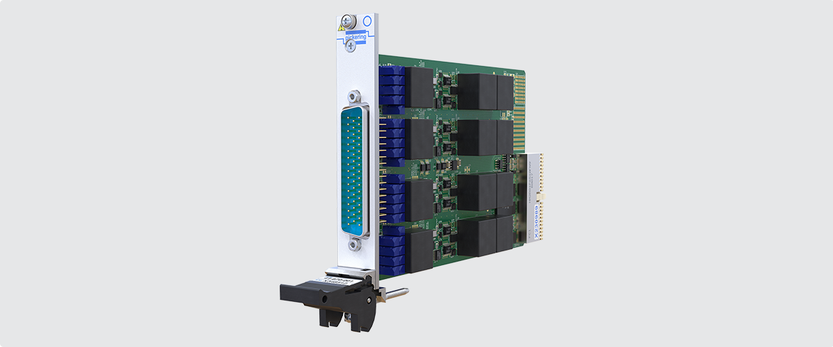
Figure 2 – This LVDT / RVDT / resolver simulator is designed for a wide range of excitation frequencies and offers a wide range of input and output voltages.
Electrification
NGA increasingly embraces electrification, with several companies developing hybrid and all-electric propulsion technologies. Also, the move away from hydraulic systems means more electrical power is needed for actuation.
The industry is moving to higher voltages to meet the power demands and because current governs the gauge and, therefore, the weight of cables. In addition, wide bandgap materials such as GaN and SiC are making switching high voltages (within inverters, for example) easier and with relatively low electrical losses.
Accordingly, whereas the DC voltage on legacy aircraft has been 28 V, NGA hybrid and pure electric propulsion systems will use between 540 and 800 VDC. And, where AC is concerned, legacy aircraft typically use 115 VAC (400 Hz), but electric/hybrid aircraft use up to 1,000 VAC (variable frequency in excess of 800 Hz).
These high voltages bring new power distribution, cable management, noise (EMC), thermal management, insulation, and safety challenges.
As per Figure 1, the HIL test system needs the ability to switch signals, some of which will be high voltage. Pickering has a comprehensive range of PXI high-voltage switching modules and LXI high-voltage modules; Figures 3 and 4 show example modules from these ranges.
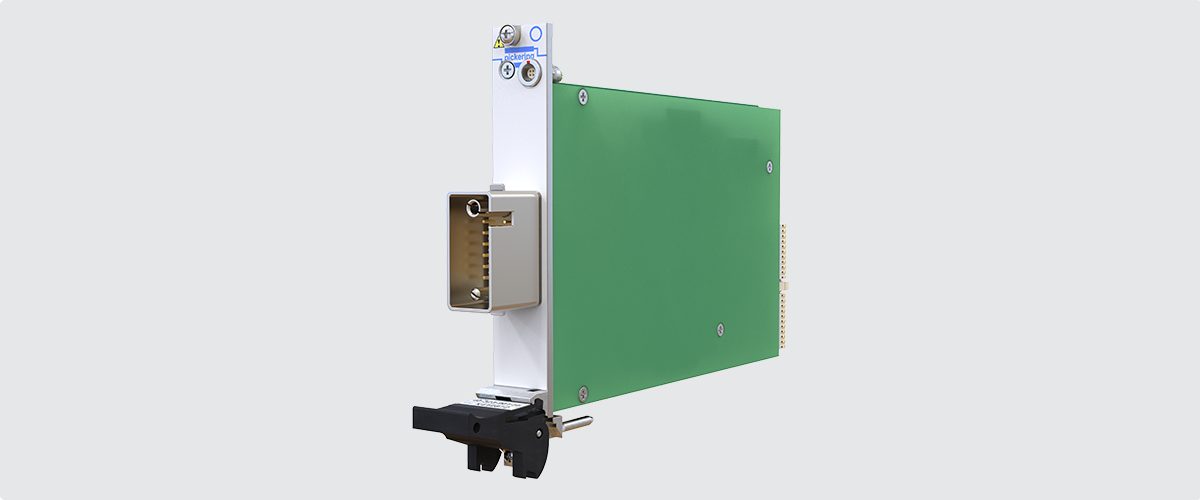
Figure 3 – The 40-323-901 (PXI) and 42-323-901 (PXIe) High Voltage Power Relay Modules can switch up to 7k VDC and are available with up to 14x SPST relays.
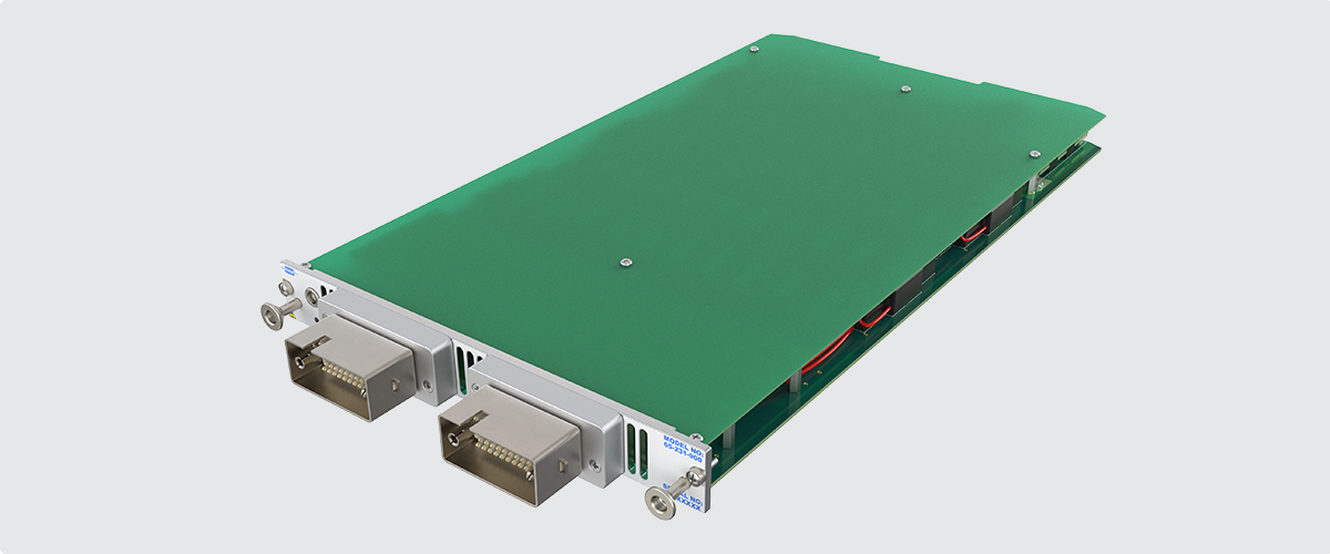
The scalable 65-231 LXI High-Voltage Multiplexer platform capable of cold switching up to 9 kV and hot switching up to 5 kV.
The company also supplies high-current switching modules up to 40 A.
Another key aspect of the greater electrification of aircraft is power storage, and several companies are looking at new battery technologies (striving for higher energy densities) and battery management systems (BMSs) that monitor and control the power going into and from battery packs, while having the resolution to monitor battery health at the cell level.
To assist in the development and verification of BMSs, Pickering offers a range of PXI/PXIe battery simulator modules. For instance, a 6-cell battery simulator (model 41-752A) is ideal for emulating the multi-cell battery packs used in NGA. Its high density and high isolation voltage barrier permit it to be used with many cells in series, enabling it to emulate a battery pack of up to 108 cells in a single PXI or LXI chassis.
For more on this subject, see the white paper “BMS Functional Verification: The Safety-First Approach”.
HIL simulation may also require simulated loads. As previously mentioned, medium-power programmable resistor modules can be used for this purpose - an example is shown in Figure 5. They can also be utilized to simulate short circuits in wiring and sensors.
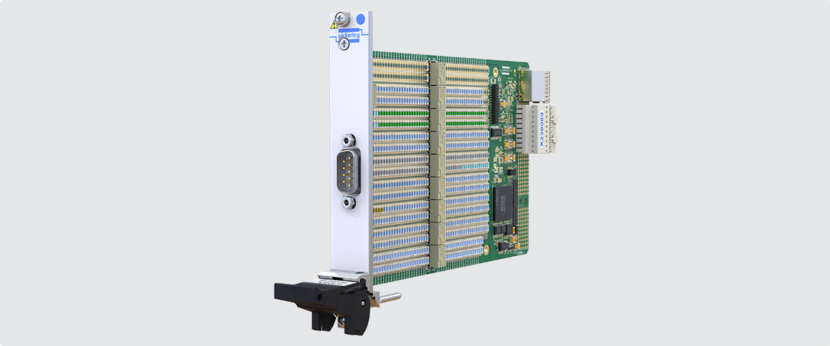
Figure 5 – The 42-254 PXIe Programmable Resistor modules have resistance ranges up to 395 kΩ and resolutions down to 0.1258 Ω.
Communications (Wired & Fiber)
NGA platforms use high-speed comms buses (sometimes multiple) for commercial aircraft avionics, cabin management, and infotainment systems. During the development and verification of an NGA module, the HIL system will need to route signals from/to other modules that are already complete or being emulated.
Pickering offers various products for serial comms bus switching, and a particularly useful one is the company’s PXI/PXIe data communications multiplexer (see Figure 6). This is suitable for switching 1 Gb Ethernet, AFDX, and future implementations of ARINC’s ADN signals. The company also supplies specific switching modules for the MIL-STD 1553 data bus.
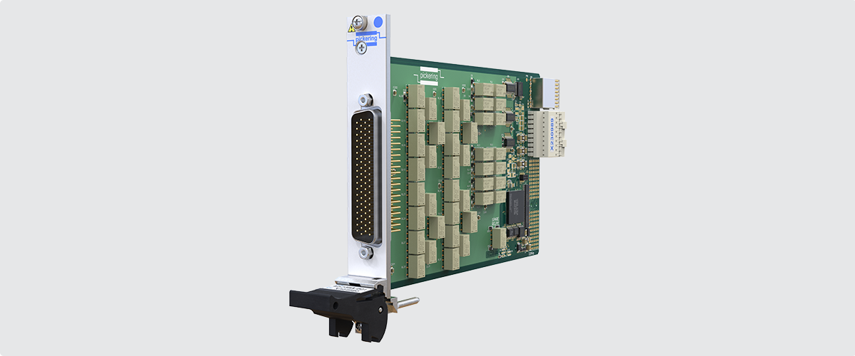
Figure 6 – The PXI/PXIe Data Communications Multiplexer can be configured under software control to provide switching (multiplexing and demultiplexing) for up to 32 differential pairs.
NGA platforms are also leveraging network technology designed for the competitive high-technology automotive industry. The Airlines Electronic Engineering Committee (AEEC) has released the ARINC 854 Cabin Equipment Network bus specification, which is based on single-pair Automotive Ethernet. This provides increased bandwidth (currently up to 100 Mbps with expectations to 1 Gbps) while reducing size, cost & weight and simplifying maintenance. The applications for ARINC 854 include cabin lighting control and passenger seat data communications, but cockpit avionics will also migrate to this new network technology.
In addition to the above copper-wired comms buses, fiber optics will be used extensively on NGA. Benefits include increased bandwidth (ideal for in-flight entertainment (IFE) and systems in large commercial aircraft), high-speed networking between avionics systems, and improved noise immunity. In the military sector, fiber’s security and resistance to interference are of great appeal.
Again, Pickering has solutions that can be used in HIL systems: the company’s PXI and LXI optical switching products. Both use micro-electro-mechanical systems (MEMS) switching technology to ensure fast and reliable switching of single- or multimode optical signals carried on fiber connections.
RF & Microwave
Commercial NGA will utilize more RF and microwave technologies for navigation, communication and radar systems (weather, collision avoidance, etc.), for example. NextGen military aircraft will use RF and microwave for the same purposes as well as target acquisition and electronic warfare (including detecting and jamming enemy radar systems).
HIL simulation for radar systems has evolved from radar jamming. Digital Radio Frequency Memory (DRFM)systems are typically used to create false targets to confuse the radar in the battlefield, but these same systems can simulate a target in the laboratory. This configuration allows for the testing and evaluation of the radar system, reducing the need for flight trials (for airborne radar systems) and field tests (for search or tracking radars), and can give an early indication of the susceptibility of the radar to electronic warfare (EW) techniques.
During the development of some NGA systems and functions, it will be necessary to interface with RF and microwave signals. Pickering has a long history of providing RF and microwave switch solutions that range from simple switch control up to 110 GHz, to fully integrated turnkey subsystems. An online graphical Microwave Switch Design Tool allows RF system engineers to design their own custom microwave switch and signal distribution system, simulate its RF electrical properties, and seamlessly collaborate with Pickering’s in-house experts to refine the design. Pickering can then provide a quotation for its manufacture, with full documentation and test.
Take a look at Pickering’s white paper “RF & Microwave Test: What is the Optimum Strategy?”
- Three different approaches to designing RF microwave switching and signal distribution subsystems that provide platform flexibility
- How to optimize your internal resources while ensuring fit-for-purpose and repeatability
- The best solution for performance, documentation and turnaround
- Ways standard and modified COTS products minimize risk and obsolescence
- Insights into the streamlined, six-phase process for Pickering’s Turnkey Service from proposal to final delivery
Signal Switching
As previously discussed, these components are essential for HIL systems in relation to high-voltage, high-current, RF/ microwave, optical signals, and serial communication buses. Digital I/O and a wide variety of analog signals (such as the industry-standard 4-20 mA, used by many sensors) will also need to be switched.
In this respect, Pickering offers an extensive range of high-density switching solutions, including high-density PXI large matrix modules (rated up to 150 V, 1 A, and 20W), 2-amp PXI large matrix modules and high-density LXI matrix solutions. The verification and diagnosis of relay faults in these complex matrices can be very time-consuming, and to ease this burden Pickering incorporates Built-in Relay Self-Test (BIRST™) hardware into most of their high-density matrices — this is used in conjunction with a free Windows software application to detect faulty relays automatically.
Similar external tools, available for all the company’s low to medium-current switching modules, are Pickering’s eBIRST™ — Switching System Test Tools. These can quickly test a switching system, diagnose any faulty relays, and graphically display the failures to simplify repair (see Figure 7).
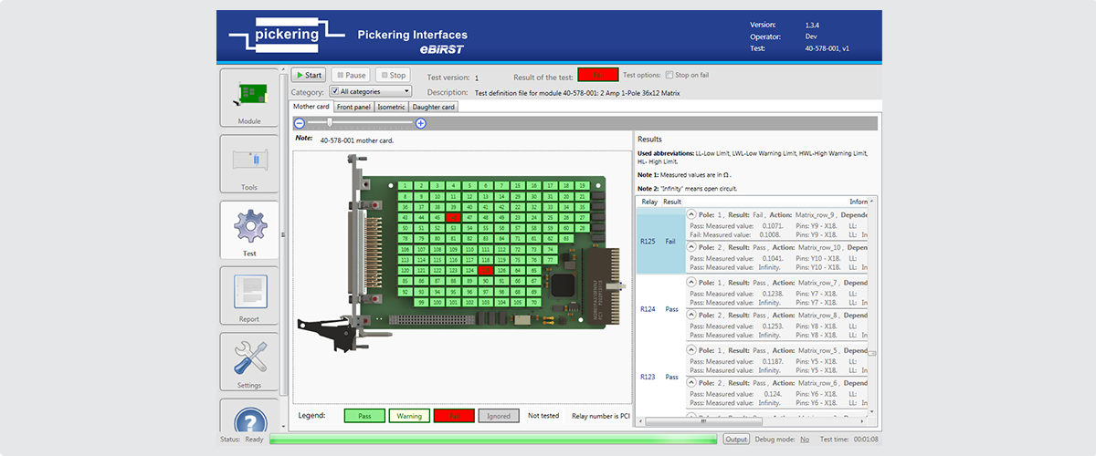
Figure 7 – When a switching system develops a fault, it causes downtime (delaying the HIL testing activities). The majority of Pickering’s switching products can be diagnosed with the company’s BIRST and eBIRST (pictured in action above) tools.
Fault Insertion
Fault Insertion can significantly simplify and accelerate HIL application testing, diagnosis, and integration work. Many of the modules described above have some built-in fault insertion capabilities, such as an LVDT’s input or output wires shorting out or a battery cell connection going open circuit.
However, due to the complexity of an NGA, the HIL system will need to be capable of injecting a variety of other faults. Pickering’s range of PXI fault insertion units (FIU) is designed for safety-critical applications where the response of a control system under development must be evaluated when crucial signals (sensor connections, for example) behave in unexpected ways.
Part of the NGA development effort, and certainly certification, will include verifying system behavior in case of networking faults. In this respect, Pickering also offers a family of PXI differential serial interface fault insertion modules. They support high bandwidth 2-wire channels and can be used to simulate common faults on AFDX networks, for example. Any wire can be set to an open circuit, and shorts can be applied across a wire pair or between pairs. Fault connections can be made to external signals via discrete fault buses, typically simulating connections to a supply voltage or ground.
For the latest ARINC 854 high-bandwidth single-pair Ethernet networks, Pickering has also fault insertion switching originally developed for automotive applications, which can seamlessly handle up to 10 Gbps data rates.
Moreover, the FIUs can switch between model-based simulations and real-life components, so as the NGA module/function comes together, it is easy to switch between the two. Also, as mentioned, some faults cannot be easily/safely injected into some real-life components; therefore, having the ability to switch back to simulations is of great benefit.
Take a look at the video “Automated Fault Insertion and its Role in Hardware-in-the-Loop (HIL) Simulation”
Along with the video, Pickering offers additional references to help you understand Fault Insertion (Fault Injection) and its role in Hardware-in-the-Loop (HIL) simulation:
- Hardware-in-the-Loop Testing - including Fault Insertion and Sensor Simulation
- PXI solutions for Fault Insertion Testing
- PXI Fault Insertion products
- Success Story - Automating Fault Insertion Tests to Improve Software Quality
- Knowledgebase articles on Fault Insertion
Additional Pickering Benefits
Having provided so many examples of hardware that can be used in a HIL system, the first benefit to discuss is Pickering’s unwavering commitment to open standards such as PXI, which boasts great modularity, close synchronization and precise timing, and LXI, which offers flexibility and ease of integration with distributed systems.
Pickering designs modular switching, simulation, and instrumentation solutions on PXI and LXI platforms, delivering scalability, flexibility, and long-term reliability. In essence, the modular nature of an NGA necessitates a similarly modular HIL system. To address this, Pickering provides customers with COTS, hybrid, or turnkey solutions customized to meet their specific requirements.
HIL systems require many high-performance connections between test instrumentation and the DUT. Pickering addresses this by specializing in custom cabling, ensuring seamless integration with in-house ATE or systems supplied by third parties.
Of particular relevance to NGA, Pickering is actively engaged in the aerospace and defense sector, supporting a wide range of companies, from emerging startups to well-established tier 1 organizations. Furthermore, Pickering’s relationships with many customers extend well beyond providing products. A prime example of their work can be found in the following case study.
Case Study: Hardware-in-the-Loop (HIL) and Real-Time Simulation Help Honda Accelerate the Commercialization of its HondaJet Echelon
Honda turned to Pickering for help in creating a system more integrated than their existing solution, one that could cope with a higher density of signals in real time. Pickering’s solution took the form of its 18-slot LXI/ USB modular chassis and a variety of simulator modules. The chassis is fully compliant with the LXI Standard 1.4 and allows 3U PXI modules to be installed and controlled through a standardized Gigabit Ethernet interface or via a USB interface.
…which illustrates the challenges and solutions involved in ensuring the HIL test system operates in real-time. Fortunately, Pickering collaborates closely with specialists in this field, such as ADI, OPAL-RT and DMC Engineering, to achieve real-time control within HIL test environments.
Explore the white paper created in collaboration with OPAL-RT, "Hardware-in-the-Loop Testing of a FADEC System"
- Learn how HIL testing produces consistent test results under real-world conditions
- Discover scalable testing methods to validate complex FADEC functionalities
- Explore traceable workflows that simplify compliance with aerospace standards
- Access methods for testing fault conditions safely and efficiently
- Understand how to identify and resolve system issues earlier in development
Not all NGA systems need to be real-time, making it important to note that Pickering supports Simulink. This allows any functional models you build or acquire to be seamlessly implemented on Windows and in Pickering’s simulation hardware.
As noted, a key aspect of NGA is the growing trend toward increased electrification. In this area, Pickering leverages its extensive experience in the automotive and EV markets. For instance, ECUs and other controllers essential to electric propulsion powertrain systems play a vital role in ensuring safe and efficient vehicle operation. Pickering supports numerous OEMs of ECUs, BMSs, and other automotive systems with HIL simulation products and services, enabling engineers to optimize control algorithms and conduct non-destructive excursion testing for unsafe external fault conditions.
Additionally, Pickering is deeply committed to obsolescence management, ensuring long-term support through strong and reliable partnerships.
Conclusion
Because of NGA’s complexities, product development and functional verification are extremely challenging. However, while voltages and bandwidths have increased and new propulsion systems are being developed, for example, the proven practice of simulation within HIL systems still holds true. Moreover, HIL simulation complements new practices such as the use of digital twins, AR, and VR.
The modularity of the hardware within HIL systems aligns seamlessly with the modularity of NGA, enabling (sub) teams to concentrate on developing specific functions even before prototype hardware is available. This approach accelerates NGA projects and reduces risks by providing valuable insights into functional behavior through HIL simulation.
Appendix
Boom Supersonics’ Overture is a supersonic airliner designed to fly at Mach 1.7. It’s intended to carry 64-80 passengers and has a projected range of 4,250 nautical miles. Boom aims to introduce the Overture in 2029, with fares comparable to business class. For further details and latest news, visit: https://boomsupersonic.com/overture
Global Combat Air Programme (GCAP) is a UK-led program involving Italy and Japan. It aims to develop a sixth-generation stealth fighter that will replace the Eurofighter Typhoon (in service with the Royal Air Force (RAF) and Italian Air Force) and the Mitsubishi F-2 (in service with the Japan Air Self-Defense Force). The UK’s contribution to GCAP is called Tempest, and it is part of the UK’s Future Combat Air System (FCAS).
NASA’s Quiet Supersonic Technology (Quesst). So far, Lockheed Martin has built a technical demonstrator called the X-59, which is designed to travel at Mach 1.4 at an altitude of 55,000 feet and create a sonic ‘thump’ rather than a sonic boom. For further details and latest news, visit: https://www.nasa.gov/mission/quesst/
Next Generation Air Dominance (NGAD) is a United States Air Force (USAF) sixth-generation air superiority initiative for a ‘family of systems’ to succeed the Lockheed Martin F-22 Raptor. Manned-unmanned teaming (MUM-T) is key to the program in that a crewed Penetrating Counter-Air (PCA) platform will be supported by uncrewed collaborative combat aircraft (CCA).


