How to setup MAX to use Pickering's Switches with NI Switch Executive
Pre-requisite: Install NI Switch Executive via the NI Package manager.
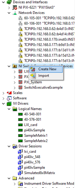
Our IVI installation pi40iv.msi places an example driver session (pi40ivSample) into the MAX configuration (see picture below). There is also an entry in the Instrument Driver Software Modules folder (pi40iv). All created devices for PI switch modules will relate to these entries.
Each instrument used must have:
A valid resource descriptor in the Hardware Assets folder(of a particular driver session) with “Simulate with” entry field set to “Don’t Simulate”(for physical connection) OR
The "Simulate with" entry field set to "Specific Driver" along with the Resource descriptor(for simulation).
Otherwise, an error will occur when creating a Switch Executive Virtual Device.

The easiest way to setup MAX for Pickering Interfaces switch modules is to Create a New Driver Session and copy, paste and change the appropriate fields from pi40ivSample. This will be described on the following pages. (Repeat the following described Step 1 to Step 5 for each module to be inserted into the MAX configuration.)
In this document, we look at Pickering cards in PXI and LXI Chassis used with NI Switch Executive via IVI drivers.
Section A: Cards in PXISection A: Cards in PXI
Step 1 - Create IVI Driver Session
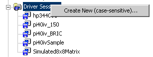
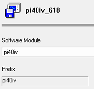
Create New Driver Session by right clicking the Driver Session folder (say, pi40iv_618).
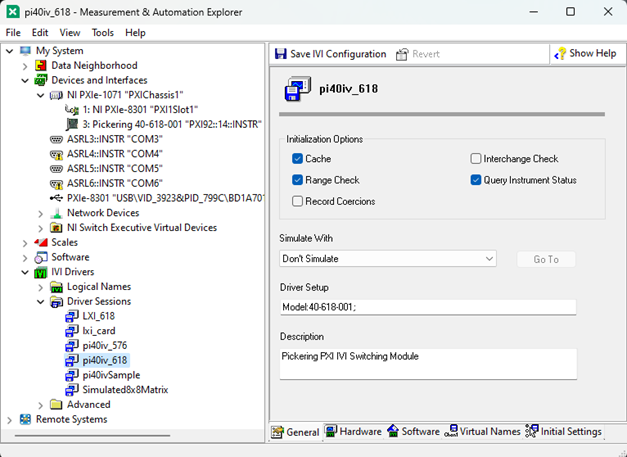
Under ‘General’ in the specific driver session tab, the most important entry is Driver Setup: Model:40-548-001
The model number entered must match exactly with a model in the Pickering card definition file pi40iv.ini which may be located in the IVI folder system, usually at C:/Program Files/IVI Foundation/IVI/Drivers/pi40iv.
To simulate the card, select ‘Specific Driver’ in the ‘Simulate With’ selection combo box. For connecting to the card, select ‘Don’t Simulate.’
Under ‘Hardware’ in the driver tab, a hardware asset with the exact resource descriptor, for each module, has to be selected. The resource descriptor for each card can be seen under Devices and Interfaces with the format ‘PXI92::14::INSTR,’ where 92 is the bus number and 14 is the device number in this case. Make sure you choose the resource descriptor correctly with respect to your setup. If required, create a new asset and change the descriptor.
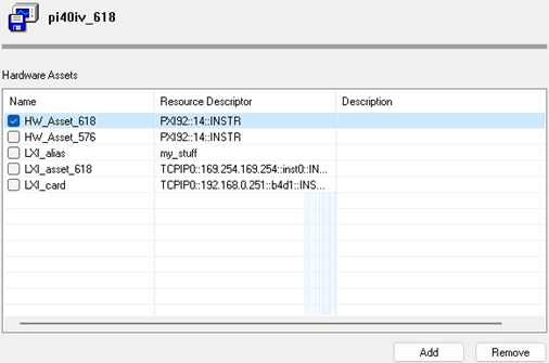
(Don't forget to check the tickbox to select the asset!)
In the driver's software tab select the pi40iv as the necessary software module.
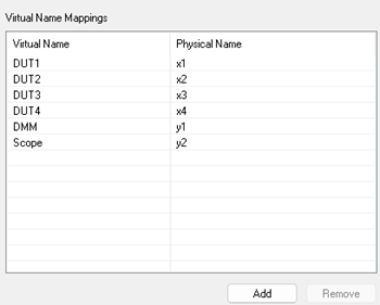
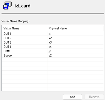
If you wish to use Virtual Names, these can be defined on the Virtual Names tab.
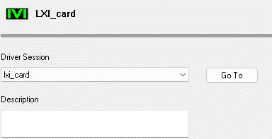
Step 2 - Create IVI Logical Name
Create New Logical Names by right clicking the Logical Names folder. A driver session for the logical name has to be selected in the consecutive window.
These logical names will appear in the later defined Switch Executive Virtual Device.
Step 3 - Create Virtual Device
Create New Switch Executive Virtual Device by right clicking the Switch Executive Virtual Device folder. Add
all necessary devices from the list.
All system modules which have to be interconnected must be listed in one device.

Step 4 - Edit the Virtual Device, adding aliases (not necessary)
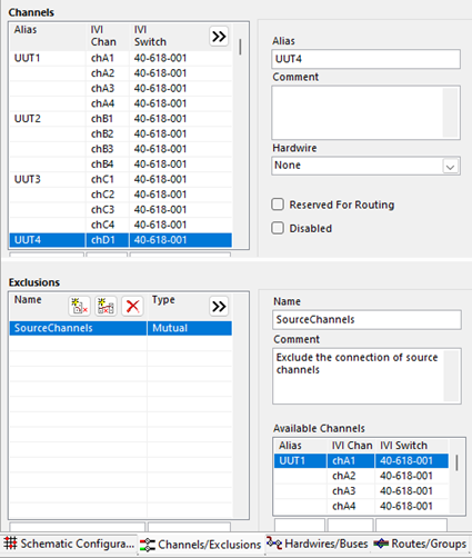
Edit the IVI channel alias names, check the channels which will be reserved for routing. In the example no exclusions are defined.
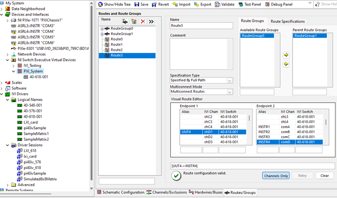
Step 5 - Edit the Virtual Device - add routes
Edit Routes and Route Groups as your connections require.
Section B: Cards in LXI via Ethernet connection
Step 1: Create IVI Driver Session
Create New Driver Session by right clicking the Driver Session folder(say, lxi_card).

Under ‘General’ in the specific driver session tab, the most important entry is Driver Setup: Model:40-576-001
The model number entered must match exactly with a model in the Pickering card definition file pi40iv.ini which may be located in the IVI folder system, usually at C:/Program Files/IVI Foundation/IVI/Drivers/pi40iv.
To simulate the card, select ‘Specific Driver’ in the ‘Simulate With’ selection combo box. For connecting to the card, select ‘Don’t Simulate.’
Under ‘Hardware’ in the driver tab, a hardware asset with the exact resource descriptor, for each module, has to be selected. Choose the TCPIP address of the specific LXI that you are connecting to, as the descriptor. If required, create a new asset and change the descriptor.
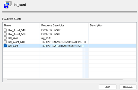
Don’t forget to check the tickbox to select the asset!
Note: The resource descriptor of the chassis is: “TCPIP0::192.168.0.251::inst0::INSTR”, and The card would be: “TCPIP0:: 192.168.0.251::b4d0::INSTR”.
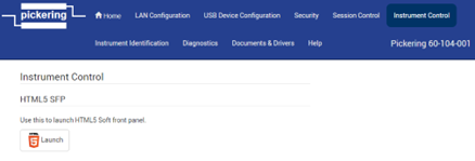
The b4 and d0 refers to the bus and device number. This can be obtained from the IP address. Instrument control - HTML5 Soft front Panel Launch
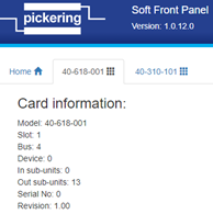
The bus and device number can be used to confirm the card in NI MAX
In the driver's software tab select the pi40iv as the necessary software module.

If you wish to use Virtual Names, these can be defined on the Virtual Names tab.
Step 2: Create IVI Logical Name
Create New Logical Names by right clicking the Logical Names folder. A driver session for the logical name has to be selected in the consecutive window.
These logical names will appear in the later defined Switch Executive Virtual Device.
Step 3: Create Virtual Device
Create New Switch Executive Virtual Device by right clicking the Switch Executive Virtual Device folder.
Add all necessary devices from the list. All system modules which have to be interconnected must be listed in one device.
Step 4: Edit the Virtual Device - add aliases (not necessary)
Edit the IVI channel alias names, check the channels which will be reserved for routing. In the example no exclusions are defined.
NOTE: Usually, the y channels will be checked for “Reserved For Routing”

Step 5: Edit the Virtual Device - add routes
Edit Routes and Route Groups as your connections require.

Section C: Cards in LXI connected via USB
Step 1: Driver session
Create a driver session(say, LXI_618).
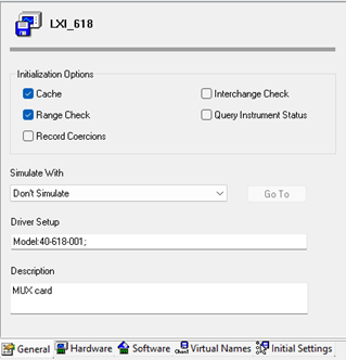
Add and tick the hardware asset
Select pi40iv for Software Module.
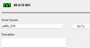
Step 2: Create Logical name(say, 40-618-001)
Select the driver session appropriately.

Step 3: NI Switch Executive Virtual Devices
Virtual Device Name: LXI_testsetup
Move 40-618-001 from ‘Available Switches’ to ‘Switches to Add’.
You can also edit the virtual device, adding Alias names for the channels.
Step 4: Add Routes
Create routes(and maybe route groups as well). (Please refer to the previous section for pictures)
Select ‘Validate’ to make sure the connections work correctly or the ‘Test Panel’ to individually evaluate the routes
Section D: Using VISA Alias
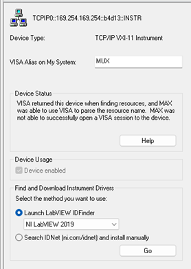
Change Visa Alias(say, MUX) Under Network Devices -> Select the TCPIP address of the device - General
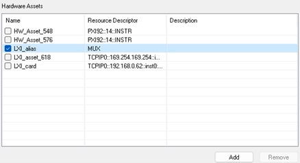
In the hardware assets, change resource descriptor to ‘MUX’
Save IVI configuration.
Go to logical name and make sure the correct driver session is selected -> Save IVI configuration.
Create the Switch Executive Virtual device -> Add IVI switch -> choose the appropriate switch(the particular logical name we had created).
Section E: When your card (“TCPIP0::169.254.169.254::b4d0::INSTR”) doesn’t appear
In the instance, where your card doesn’t appear under the Network Devices, we can manually add it.
Go to Network Devices -> right click -> Create New VISA TCP/IP resource -> Create New
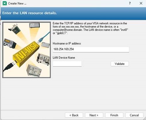
Enter the IP address and click validate which will help point to the connected chassis.
Else, manually add by entering ‘inst0’ in LAN Device Name and click Finish.
(If you click validate, you might see an error in case of the card. This is fine, you can proceed with the steps)
Then add the device in a similar manner with ‘b4d0’ in LAN Device Name and click Finish. (b4d0 is in my case, check the bus and slot number and enter accordingly)
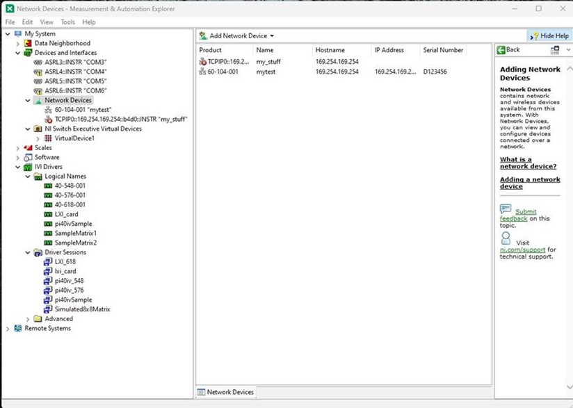
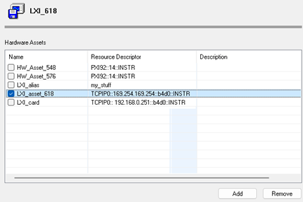
Now, the VISA alias for the card is ‘my_stuff’.
Go to the driver session and change the resource descriptor to ‘my stuff’

Save IVI configuration -> Go to Logical name -> Save IVI configuration
Add new Switch Executive - Add IVI Switch - Select the ‘logical Name’ which points to the appropriate ‘Driver session’.
Section F: Check if setup is working using NI Switch Executive
The card being used here is 40-618-001.
Now, we have to create a route group or route (as many as you want for testing).

I have just created one(chA1 -> comA).
Go to the test Panel.
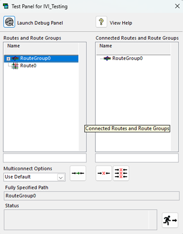
Select the particular Route Group or Route and click on the green arrow This will take it to the ‘Connected Routes and Route Groups’ column.
If you are using a test card, you will be able to see the LED turn on. (To turn it off, select it from the second column and press the red x).
Section G: Check if setup is working using NI Teststand
(The below image might not reflect the latest version.)
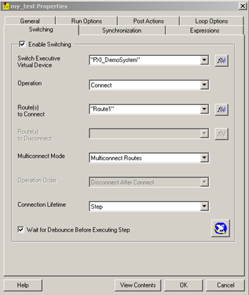
Launch TestStand. Create a simple test sequence with one test step. Right click the test step and select Properties.
In the Switching tab the required switching can now be selected.