
Contents
30 Sep 2025 • 15 minutes
Hardware-in-the-Loop Testing of a FADEC System
Developed in collaboration with OPAL-RT, this white paper will help you access proven techniques and strategies to reduce risk, improve accuracy, and streamline FADEC validation in aerospace applications.
Executive Summary
Full Authority Digital Engine Control (FADEC) systems are complex, safety-critical embedded controllers used in modern commercial and military aircraft to control all aspects of engine performance. To verify their functionality under a wide range of real-world conditions, Hardware-in-the-Loop (HIL) simulation offers a powerful, efficient, and certifiable validation strategy.
This white paper presents a collaborative HIL solution by OPAL-RT and Pickering. Together, OPAL-RT’s leadership in real-time simulation and turnkey test benches, combined with Pickering’s expertise in precision signal switching, sensor simulation, and instrumentation, deliver a powerful, scalable, and certifiable environment for comprehensive FADEC verification.
What is FADEC?
A Full Authority Digital Engine Control (FADEC) system supervises engine parameters and control operations in real time, ensuring optimal performance, fuel efficiency, reduced pilot workload, and enhanced system reliability.
Many engine OEMs widely adopt FADEC in their products. For example, Rolls-Royce incorporates FADEC into its EJ200 engine (powering the Eurofighter Typhoon), its Trent family of engines, and its M250 turboshaft engine used in helicopters such as the Sikorsky S-76.[SE1.1]
By minimizing mechanical complexity and improving integration with aircraft avionics, FADEC enhances maintainability and long-term performance. Given its full authority over the engine, it must meet strict certification standards, including DO-178C and DO-254, reinforcing the need for robust development and verification strategies, such as HIL simulation.
The collaboration between Pickering and OPAL-RT delivers a complete, scalable HIL test platform, combining real-time simulation, advanced sensor/load emulation, communication bus validation, and robust system integration. This solution accelerates FADEC development, improves system reliability, and ensures compliance with the aerospace industry’s highest standards.
EEC, DEC, or FADEC
Understanding the differences among engine control systems clarifies the increasing need for comprehensive testing.
- Electronic Engine Controls (EECs) primarily utilize analog circuitry to manage inputs and outputs.
- Digital Engine Controls (DECs) incorporate processors to perform control tasks digitally but maintain limited engine authority.
- FADECs offer full, autonomous control over engine performance, integrating digital monitoring and command for all operational parameters.
The approaches discussed herein, while focused on FADEC, are broadly applicable to EEC and DEC systems as well.
How Does FADEC Work?
A FADEC system constantly monitors a wealth of inputs, receives commands from the cockpit, communicates with other systems on the aircraft, and drives outputs. Let’s discuss each of the FADEC system’s interface types.
Inputs
A FADEC system continuously monitors a wide range of sensors and inputs:
|
|
Other inputs come from the cockpit, most notably engine start and throttle control.

Figure 1: An illustration of the data coming from the engine.
The FADEC system accepts a mix of analog and digital signals. The analog inputs will either be voltage or current (either arbitrary or industry standard 4-20mA), while digital inputs might also include pulse-width modulation (PWM) signals.
Outputs
Many of the FADEC system’s outputs drive actuators which, as readers will be aware, convert an electrical signal into mechanical movement, which can be used to adjust the position of a valve, for example.
Most of these actuators are fitted directly onto the engine. For instance, an actuator-driven fuel metering valve regulates the amount of fuel entering the combustion chamber, and compressor bleed valves adjust air pressure within the engine for different phases of flight; takeoff, climb and cruise. As for landing, thrust reversers are used to help decelerate the aircraft, and the FADEC controls the hydraulic actuators that alter the engine's direction of thrust to assist in braking.
Figure 1: A JASC fuel metering valve assembly (FMVA) incorporating an electro-hydraulic, 4-way fuel-metering servo, a pressure compensating by-pass valve, a pilot-operated solenoid, and a shut-off valve into a single integrated package. Source = https://jasc-controls.com/fuel-metering-valve/
Additional actuators commonly installed may include variable area nozzle (VAN) actuators, which adjust the exhaust flow area to regulate exhaust gas output. This regulation helps optimize thrust, enhance fuel efficiency, and reduce noise levels. Another example is turbine blade position actuators, which adjust the angles of turbine blades in response to power demands. These actuators improve engine performance, enhance efficiency, and reduce excessive wear on components.
Also, although not driving an actuator, an essential output from the FADEC is to the ignition system that controls the ignition plugs, ensuring they are activated at the right time during engine start-up, to facilitate a smooth and controlled engine start.

Figure 2 – A JASC fuel metering valve assembly (FMVA) incorporating an electro-hydraulic, 4-way fuel-metering servo, a pressure
compensating by-pass valve, a pilot-operated solenoid, and a shut-off valve into a single integrated package.
Source = https://jasc-controls.com/fuel-metering-valve/
On another note, FADEC systems often communicate with sensors and actuators using the industry-standard 4-20mA analog communications protocol.
The complexity and diversity of FADEC’s real-time input/output interactions make HIL simulation, through OPAL-RT's real-time systems and Pickering’s I/O emulation, a perfect validation strategy.
Communication Buses
FADEC system interface buses include ARINC 429, 629, and 664 Avionics Full-Duplex Switched Ethernet (AFDX)[DH3.1], which are widely used in aviation. They allow for the transmission of data between the FADEC system and other avionics systems, such as the cockpit displays, I/O modules, flight management systems (FMS), or other subsystems. Ethernet and CAN bus are also popular buses.
Military platforms will use a MIL-STD-1553 bus. So too might some commercial platforms, as the bus is used for real-time, two-way communication between the FADEC and other systems in the aircraft. It is often used for critical communication in aircraft for system monitoring and control.
In some instances, more basic buses might be between the FADEC and other systems. These include RS-232 (typically used for lower-speed, short-distance communication—up to 50 feet - point-to-point communication, with a single transmitter and receiver) and the generally more robust RS-485 (designed for longer distances—up to 4,000 feet—and multi-point communication), which multiple devices can share.
In HIL simulation, these buses must be accurately replicated. OPAL-RT supports these protocols through real-time interfacing, while Pickering complements the system with differential signal routing and fault insertion modules. Together, they ensure full validation of communication behavior under operational and fault conditions.
FADEC and Power Generation
FADEC governs the engine’s performance to ensure sufficient and stable power generation, which in turn supports the airframe's electrical, hydraulic, pneumatic, and mechanical systems. By optimizing engine efficiency and ensuring safe, reliable power delivery, FADEC plays a crucial role in managing the aircraft’s overall power systems and enhancing operational safety and performance.
It adjusts the engine power to meet the aircraft's changing demands for electrical power and helps manage engine load, ensuring the engine can provide adequate power to the aircraft’s electrical systems without overloading or underperforming.
Efficient power management, guided by FADEC, results in better fuel consumption and more consistent power for the aircraft’s electrical and mechanical systems.
In addition, the FADEC system incorporates safety features that ensure that the engine maintains appropriate power even in case of a system failure. For example, if one engine fails, FADEC can help redistribute power or manage performance to ensure the remaining systems are functioning properly and the aircraft remains controllable.
FADEC's communication with power distribution systems helps prevent overloads by carefully regulating how power is allocated to various systems across the airframe.
Effective power regulation reduces fuel consumption, prevents overloads, and enhances operational safety. HIL simulation replicates these dynamics, enabling FADEC developers to validate engine response to varying load conditions safely and reliably.
A Real-Time Embedded System
FADEC is inherently a real-time system, requiring deterministic responses to critical sensor inputs and actuator commands.
OPAL-RT’s real-time simulation platforms, running on robust real-time operating systems such as RTLinux, ensure the FADEC’s timing requirements are properly modeled and tested. These systems support precise response times, concurrency management, and complex multitasking needed for aerospace applications.
Real-time HIL simulation enables early detection of timing issues and validates the FADEC’s ability to meet strict aerospace industry timing and safety standards.
FADEC Design and Verification with HIL
Hardware-in-the-loop (HIL) is a technique in which a system's real-world operating conditions are emulated using hardware I/O and a computer-controlled test system.
For the development of a FADEC system—or ECC, DEC, or any other system on an aircraft for that matter—HIL provides stimulus to the design under test (DUT). It does this by replicating the outputs and response characteristics of everything the DUT expects to see as inputs, by placing emulated loads on the DUT’s outputs, and by interfacing with the DUT via its communications channels.
HIL solution eliminates reliance on physical engine testing for some scenarios, allowing engineers to identify hardware and software integration issues earlier in the development cycle, reducing costs and time-to-market for FADEC systems and similar aerospace technologies.
The Benefits of HIL Include:
- Cost Savings. Evaluating FADEC design iterations using simulation techniques means fewer prototypes (and physical test rigs) are needed.
- Time (and further cost) savings are realized by testing earlier in the development cycle because bugs can be identified and fixed before they have a chance to migrate further into the design flow.
- Safety (and further cost savings). Operating under real-world conditions, such as flying at altitude or under temperature extremes, can be verified without risking damage to equipment or the cost of hiring environmental test chambers.
- Fault injection. This is the introduction of faults, such as signals lost through open- and short-circuits, unresponsive hardware (e.g. stuck actuators) and corrupted data (such as lost data packages). It is much easier to simulate these faults rather than physically create them. It is safer too if the test condition involves high voltages, for example.
- Other parts of the platform (e.g. sensor modules) might also be under development and unavailable to connect to the FADEC. However, their intended characteristics are known and can be modeled/simulated.
In addition to the above benefits, HIL also allows for partial testing. For instance, a sub-team might be focused on developing a software module for engine temperature management. They can connect all the temperature-related hardware to a testbench connected to a computer in which reside models of engine dynamics, such as turbine and compressor behavior, fuel and airflow, and thermodynamic and mechanical parameters.
OPAL-RT’s real-time simulation platform provides accurate models of engine thermodynamics, fluid dynamics, and control logic, while Pickering’s simulation and fault insertion hardware replicates sensor inputs, actuator loads, and fault conditions. This joint solution enables early validation, fault injection, partial and full system verification, and rigorous certification testing — all in a repeatable, safe, and cost-effective environment.
HIL simulation allows the development of the FADEC system to be split into separate tasks, which is extremely efficient because the sub-teams can work relatively independently (i.e., they do not have to wait for other sub-teams to complete their tasks).
For the verification of the FADEC system, traceability is key, particularly in such a heavily regulated industry. The HIL system software comprises scripted test cases and sequences, and the results of all tests can be recorded. Moreover, many measurements can be taken from emulated loads that cannot easily be taken with real-life loads.
And, because everything can be recorded, test conditions and procedures can be replicated to verify future upgrades to the FADEC system. In essence, HIL testing is an efficient way of verifying the integrity of a product design during its development. This will include modifications being made to the design as it evolves.
What is Needed in HIL Simulation for FADEC
The heart of the HIL environment is a host computer (for test management and execution) paired with a real-time controller (containing environment and engine behavior models). There will also be a host of inputs, outputs and interfaces – simulated/emulated versions of everything discussed in "How Does FADEC Work? " section above.
Break-out boxes (BOBs) are also an essential part of the HIL, as they provide easy manual access to signals for test and measurement purposes (e.g., connecting an oscilloscope) and facilitate fault insertion.
OPAL-RT provides real-time simulation and bench integration, while Pickering’s modular hardware covers the broad range of sensor and load simulations required.

Figure 3 – The architecture of the HIL test system.

Figure 4 - An overview of OPAL-RT's HIL solution
Real-Time Simulation
OPAL-RT’s real-time platforms like the OP5707XG provide powerful and scalable environments to simulate complex thermodynamic and mechanical engine models with strict timing constraints.
It supports FPGA-based I/O processing and allows connectivity to Pickering’s PXI- or LXI-based simulation modules.
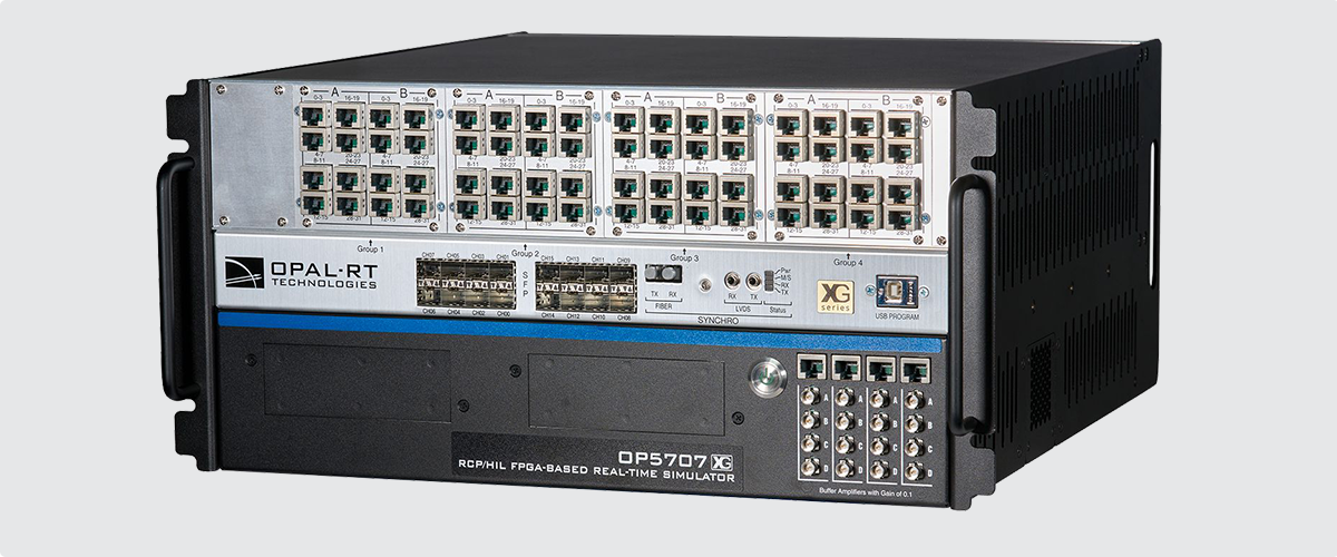
Figure 5 – The OPAL-RT OP5707XG features an Intel® Xeon® processor, up to 16 GB RAM, a 250 GB SSD, four Ethernet ports (two at 1 Gbps, two at 10 Gbps), USB 3.2 ports, HDMI and VGA outputs, and a Virtex®-7 FPGA for sub-microsecond real-time simulation.
It includes four Ethernet ports (two at 1 Gbps and two at 10 Gbps), two USB 3.2 Gen 2 Type-A ports, and both HDMI and VGA video outputs. The system also integrates a Xilinx® Virtex®-7 FPGA, supporting real-time simulation with time steps as low as 145 ns.
Temperature Sensor Simulation
Engine temperature sensors, including thermocouples and RTDs, are crucial to FADEC operation.
Pickering supplies PXI modules that can accurately simulate thermocouples and RTDs, ensuring non-linearities, reference temperatures, and fault conditions are properly represented.
This allows the FADEC system to be validated for both normal and extreme thermal conditions without real engines.
Examples of thermocouple simulators are Pickering’s 41-761 modules, which provide 8, 16, 24, or 32 isolated source channels with outputs up to ±100mV and accuracies to 0.1%±5µV.
RTDs, which are more accurate than thermocouples, might also be fitted to the engine. However, they have a limited temperature range and could be used for measuring air intake temperature, for instance. Simulation modules are available that can accurately simulate a range of RTD types, and most achieve the range/resolution required using programmable resistor ladders, as illustrated below:
Pickering’s PXI modules simulate a range of critical engine sensors, including RTDs, thermocouples, strain gauges, and pressure sensors, with high accuracy and fault insertion capabilities that enable developers to validate FADEC operation across a variety of realistic scenarios without requiring physical sensors.

Figure 6 – A simplified illustration of an RTD simulator channel. Bypassing some resistors and including others in the ladder means several resistances can be achieved - though there is a trade-off between range and resolution.
As an example, Pickering’s PXI RTD Simulator series (40-263) has module variants
to simulate up to 24off PT100, PT500, or PT1000 RTDs from -150 °C to >+850 °C, with 0.1% accuracy and simulated temperature
resolution of <0.03 °C.
Load (Resistance) Simulation
Load resistors simulate electrical characteristics seen by the FADEC under various conditions.
Pickering’s programmable resistor modules simulate a range of resistances with integrated open and short circuit fault simulation, enabling developers to validate system responses to realistic dynamic loads. In this respect, PXI precision programmable resistors are available with resolutions down to 2mΩ and accuracies down to 0.03%, together with medium power modules that can handle up to 15 W.

Figure 7 – Pickering Interface’s PXI/PXIe 15 W Programmable Resistor Modules can be programmed in increments down to 0.125 Ω with resistance values from 1 Ω to 395 kΩ depending on variants.
Position/Displacement Simulation
Key moving parts in an engine, such as fuel valves and compressor vanes, are monitored using:
- LVDTs (Linear Variable Differential Transformers)
- RVDTs (Rotary Variable Differential Transformers)
- Resolvers
Pickering’s PXI simulation modules replicate these transducers accurately, providing essential position feedback to the FADEC during HIL testing.
Pickering’s LVDT, RVDT, Resolver Simulator Module (41/43-670) is available with up to four banks, each capable of simulating the output of a single 5-wire or 6-wire VDT or resolver, or dual 4-wire LVDT/RVDT utilizing a shared excitation signal. This allows the module to simulate up to four channels of 5-wire or 6-wire, or eight channels of 4-wire. High-speed variants allow resolver output speeds of up to 130 kRPM to be simulated.

Figure 8 – The LVDT, RVDT, Resolver module (41/43-670) simulates up to four 5-wire or 6-wire VDTs/resolvers or eight 4-wire LVDTs/ RVDTs with a shared excitation signal.
Data Communications Multiplexing
Communication buses such as ARINC 429, MIL-STD-1553, CAN, and AFDX carry critical data between FADEC and other aircraft systems.
Pickering’s high bandwidth differential multiplexer and fault insertion modules can transparently route these data traffic signals, ensuring the FADEC’s communication interfaces are validated under realistic load and fault conditions.
Figure 8: The PXI Data Comms Multiplexer (40-736-001) supports switching for up to 32 differential pairs and simplifies Ethernet crossover simulation.
The PXI data comms multiplexer (40-736A-001) can be configured under software control to provide switching for 32 differential pairs, 16 dual differential pairs, and eight quad differential pairs. To support Ethernet applications, the design includes a switching network that simplifies the swapping of Tx and Rx pairs to simulate the effect of Ethernet crossover cables.

Figure 9 – The PXI Data Comms Multiplexer (40-736-001) supports switching for up to 32 differential pairs and simplifies Ethernet crossover simulation.
Discrete I/O Simulation
Discrete signals such as switches, relays, and simple status indicators are essential in FADEC operation.

Figure 10 – Industrial digital I/O family for digital signal generation and sensing, for fault-protected testing applications.
Pickering’s PXI Digital I/O modules emulate discrete digital signals reliably and are controlled dynamically during HIL testing to verify FADEC responses. They deliver high density (up to 128 input or 64 output channels), with expanded voltage (up to 300 V input or 60 V output) and current ranges (up to 2 A output), and programmable input logic thresholds—all in both PXI and PXIe form factors.
Strain & Pressure Sensor Simulation
Pressure readings are vital to engine control.
Pickering’s PXI current output modules simulate 4-20mA transducer and sensor signals, with the capability to introduce faults such as open and short circuits. This enables full validation of the FADEC's pressure sensing and reaction systems. Pickering also supplies PXI strain gauge simulators which accurately emulate both strain and pressure sensors in a balanced bridge configuration.

Figure 11: The Analog Output Current Loop Simulator (41/43-765-004) consists of up to four 16-bit, digital-to-analog converters (DACs), capable of creating four current outputs each.
Signal Breakout and Fault Insertion
Fault injection is essential to verify system safety and redundancy strategies. Pickering’s Modular Breakout System (MBOS), developed originally with OPAL-RT, combines a manual Break-out-Box feature set with the added flexibility of an automated Fault Insertion Unit. It can house a range of PXI fault insertion modules that allow automated dynamic fault insertion directly at the electrical interface between the FADEC and simulated environment. Multiple fault types, such as open circuit, short circuit, or cross-connection can be introduced safely and systematically.

Figure 12: By mating the FIU chassis directly to the BoB using plug-in modules, cabling is minimized, creating a more compact, reliable design and improving signal integrity.
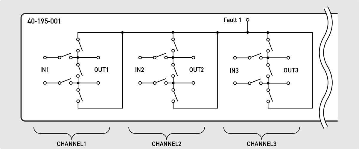
Figure 13: Channel 1 can simulate open circuits, shorts, or faults between a sensor output (IN1) and the FADEC input (OUT1).
IN1 might be a complementary-pair signal from a sensor, and OUT1 might be the FADEC’s input expecting to see that voltage. Channel 1 can be controlled such that either or both signal’s component parts can be made open circuit. They can also be shorted together and shorted to a “fault bus” (which might be set to 0V, for example, to replicate a short to ground).
System Integration and Control
Successful HIL simulation demands robust system integration.
OPAL-RT provides fully integrated benches, including:
- Real-time simulation computers
- FPGA I/O expansion units
- Custom cable harnesses and interface boxes
- Full traceability and automated reporting
Pickering’s switching, simulation and instrumentation modules, together with their standard/custom cabling and interconnection accessories, seamlessly integrate via PXI/LXI standards and are fully compatible with OPAL-RT’s real-time control frameworks. Together, they deliver a turnkey HIL test system that enables the customer to follow through the aerospace certification requirements like DO-178C and DO-254.

Figure 14: This diagram illustrates a complete HIL simulation environment, with light blue highlighting the elements provided by Pickering and dark blue indicating components typically delivered by OPAL-RT. Both companies offer complementary technologies that, when combined, form an integrated and robust HIL solution.

Figure 15: OPAL-RT’s turnkey solutions undergo a preliminary design review (PDR), critical design review (CDR), and factory acceptance test (FAT)
Through its proven experience in turnkey aerospace test benches, OPAL-RT ensures seamless integration between real-time simulation platforms and Pickering’s hardware modules.

Figure 16: OPAL-RT’s test bench can be fully customized to test not only the FADEC but also any actuator, valves and sensors
Each OPAL-RT test bench includes at least one state-of-the-art real-time simulator, connected to the device under test by custom mapping boxes and cable harnesses, precisely designed by our experts for each customer's specifications. For further testing customization and facilitation, many OPAL-RT and third-party systems, including fault insertion units (FIUs), load boxes, break out boxes (BOBs), battery simulators and programmable resistances, are available. All test benches are certified to meet electrical safety standards prior to shipping.
The OP8600 Interconnection Unit (or Mapping Box) by OPAL-RT allows signal routing and signal conditioning that can be fully customized to match customer needs.
OPAL-RT’s real-time simulation platforms, such as the OP5707XG, support precise modeling of complex thermodynamic and mechanical engine behavior, with time steps as low as 145 ns… ensuring compliance with strict timing and safety standards required for aerospace applications.
Summary
FADEC systems are highly complex, safety-critical embedded systems designed to operate in harsh environments. HIL (Hardware-in-the-Loop) simulation replicates this environment, enabling engineers to test system responses to real-world engine behavior, sensor inputs, and actuator outputs—without requiring a fully operational physical engine.
With HIL setups, engineers can efficiently test and refine FADEC algorithms, configurations, and parameters. This iterative process is faster than testing on an actual engine, allowing engineers to identify hardware and software integration issues earlier in the development cycle. By addressing problems early, teams save time and reduce the costs associated with late-stage changes.
HIL simulation minimizes reliance on physical engine testing, which can be both risky and costly. Simulating engine behavior provides a controlled environment for testing extreme or failure conditions safely. Scenarios that would be challenging, dangerous, or expensive to replicate on physical hardware can be tested virtually, ensuring the FADEC system reacts appropriately under real-life failure conditions.
Additionally, HIL simulation supports regulatory compliance by generating detailed records of tests and results. These records provide essential traceability and demonstrate that the system has been thoroughly tested in a controlled, repeatable manner.
The collaboration between OPAL-RT and Pickering delivers a complete, scalable HIL test platform combining real-time simulation, advanced sensor/load emulation, communication bus validation, and robust system integration. This solution accelerates FADEC development, improves system reliability, and ensures compliance with the aerospace industry's highest standards.
About Pickering Interfaces
Pickering Interfaces designs and manufactures modular signal-switching, simulation and instrumentation products for electronic testing and verification. With a focus on aerospace and safety-critical applications, Pickering’s PXI and LXI-based systems offer unmatched flexibility, performance, reliability and longevity. The company also manufactures complementary standard and custom interconnection products to streamline system integration.
About OPAL-RT TECHNOLOGIES
OPAL-RT TECHNOLOGIES is a global leader in real-time simulation and Hardware-in-the-Loop (HIL) solutions for aerospace, automotive, and power systems.
OPAL-RT’s turnkey aerospace benches, validated through thousands of operational hours worldwide, integrate custom-built real-time simulation platforms, high-fidelity I/O systems, and powerful testing automation tools — ensuring compliance, safety, and innovation for critical control systems like FADEC.


