Failsafe or Latching Relays for Electronic Test
Relay actuator types in electronic test can generally be separated into two varieties, failsafe and latching. This article will concentrate on microwave relays, but the general observations can also be applied to other relay types. The following observations assume that the relay is fully operational. For example, a defective relay with a stuck / welded contact will not follow the characteristics outlined in this article.
Failsafe Relays
This actuator type is energized when a drive signal is applied to the coil, resulting in the contact(s) changing state. The relay will return to its default unpowered state when the control signal is removed. Power will be dissipated by the coil while the control signal is applied, resulting in heat being generated in addition to any dissipation caused by the applied signal(s).
Latching Relays
By contrast, latching relays are operated by a pulsed control signal that alters the contact state. The contact(s) will remain in the same state until another control signal is applied, even when the system power is removed.
Short-duration pulse signals minimize the coil power consumption and reduce the heating effect.
Due to the additional complexity of the internal construction, latching relays tend to be higher in cost when compared to failsafe relays.
In addition to the failsafe / latching actuator choice, latching relays tend to be offered with various other options relating to the control interface, such as self-cut-off and automatic reset. These options can aid with the control method but attract further price premiums.
Control Interface
The internal construction of the two actuator types does vary in one fundamental way, the number of coils per contact. Failsafe relays have a single coil, whereas latching relays have two coils, one for “set” and the other for “reset” please refer to the images following for details.
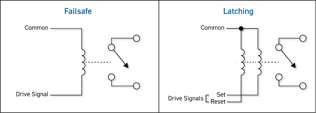
For SPnT type relays, one “set” driveline is required per contact, and some versions use a single “reset” line for all contacts, while others have a separate “reset” line for each contact. The single reset line versions reduce the control complexity as “contacts + 1” (SP6T = 7) drivelines are required, but the reset current will be higher because multiple coils are energized simultaneously. The separate reset line models reduce the operating current as just a single coil is being driven but increases control complexity as “contacts x 2” (SP6T = 12) drivelines are required.
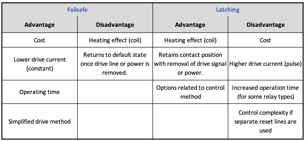
Advantages & Disadvantages
As with most components where options are available, there will be advantages and disadvantages associated with each type. This section provides some typical information to be considered that may assist with selecting the actuator type. Please note that the below is intended to be a guide only, and a detailed review of the specific parts should be performed before selecting a relay.
How to choose?
The selection of the actuator type is dependent on various factors, some are application-specific others are commercial. It is not possible to provide definitive selection criteria for every situation, but this section provides some guidelines.
It should be considered that the RF performance is identical irrespective of actuator type, the differences relate to the control interface only.
Failsafe relays have a known default state, typically open circuit, at power-up allowing users to be aware of signal connectivity while the test system is being initialized. The default state, typically, ensures that there are no connections present however in the case of terminated relays all channels will be automatically terminated in the characteristic impedance. The shorter operation time of some failsafe relay types can also contribute to reducing test cycle time allowing greater throughput of a test system.
Latching relays tend to be chosen by users that need to ensure the contact state does not change unless commanded. For example, the relay must retain its position in the event of an unintended power failure as returning to the default condition could result in high power signals being routed to sensitive equipment potentially causing damage. In addition, the reduced heating effect of the pulsed coil(s) can be beneficial as the cooling capabilities can be reduced in the test system.
Summary
In conclusion, the choice of failsafe or latching is influenced by several aspects all of which need to be considered in relation to the required characteristics/requirements of the test system. For many applications, the lower cost and known default state of the failsafe relays have proven to be the best fit for test systems.