
Contents
14 Mar 2024 • 15-18 minutes
Next-Level Testing: The Role of LVDT, RVDT and Resolver Simulation
Discover the role of LVDT, RVDT & Resolver simulation in next-level testing & learn how simulating modular simulation can greatly aid the development of systems to measure displacement or rotational position and velocity .
This white paper describes how simulating the behavior of LVDTs, RVDTs and resolvers can greatly aid the development and functional verification of systems that rely on these components for displacement or rotational position/velocity measurement. We also outline the research and development of Pickering Interfaces’ PXI and PXIe LVDT/RVDT/Resolver Simulator Modules.
LVDT
A linear variable differential transformer (LVDT) is an electromagnetic transducer used to measure displacement. Electrically, it is similar to a standard transformer with a primary winding and two series-connected secondary windings. All three windings are made around a tube that houses a movable cylindrical ferromagnetic core – see Figure 1. Within the LVDT, the core is connected to a shaft. The shaft itself could be the measurement target or be in contact with a surface (or connected to a structure), the position of which needs to be determined.

Figure 1 – Illustration of the electrical connectivity (left) within and the cross-section (right) of an LVDT.
The secondary windings are made such that one will output in phase with any AC excitation on the primary winding, while the other will be 180 degrees out of phase. When the LVDT’s core is axially central, the secondary windings will have equal amplitude but 180 degrees out of phase; this means that when taken together, there will be no output from the secondary windings; this is termed the null position. When the core moves in a positive direction, the amplitude on one secondary winding will increase and the other will decrease; conversely, when the core moves in the negative direction, the amplitude of one secondary winding will decrease, and the other will increase. Through signal conditioning—essentially comparing the secondary windings’ outputs against the primary excitation—a proportional voltage can be output with an amplitude and phase representing the core’s distance and directional displacement relative to the null position.
There are three variations of LVDT secondary winding connections. Some manufacturers internally connect the two secondaries to create a 4-wire LVDT. This configuration requires a simpler signal conditioner to process the displacement measurement while minimizing the interconnecting cabling. Alternatively, a 5-wire construction provides access to the secondary transformer center tap as a reference signal, allowing the signal conditioner to minimize the temperature sensitivity and phase differences between the primary and secondary coils. There is also a 6-wire configuration, which is less common but allows the user to monitor both secondary coils independently. These configurations are illustrated in Figure 2:

Figure 2 – 4, 5 and 6-wire LVDT configurations.
LVDTs are used in many industry sectors, including aerospace, petrochemical, and metrology. Applications include satellite controls, determining valve and actuator positions, vibration monitoring and profiling the surfaces of structures.
RVDT
A rotational variable differential transformer (RVDT) is similar in operation to an LVDT but is used to measure angular as opposed to linear displacement. It also has a primary and two secondary windings, but these are cam-shaped as an RVDT body is typically a short/squat cylinder rather than the longer, tube-shaped LVDT. Again, the core is connected to a shaft, but the relationship is perpendicular rather than in-line, and the shaft twists rather than moves in and out, as illustrated in Figure 3.

Figure 3 – Illustration of the electrical connectivity (left) within and the cross-section (right) of an RVDT.
Though an RVDT’s shaft can rotate 360 degrees, typical devices have a limited angular measurement range of up to ±80 degrees. The null position is in the center of the device’s range, and external signal conditioning is used to represent the direction and angle of the shaft’s rotation from the null as a proportional output voltage.
As with LVDTs, RVDTs are also used to determine the positions of valves and actuators. They also determine the position of joysticks, wheels, dials and other control interfaces. Accordingly, they too have uses in aerospace, petrochemical and industrial processing.
Resolver
A resolver is also an electromagnetic transducer and, as with an RVDT, can be used to determine the angular position of a rotor shaft enclosed in a cylindrical stator housing via the transformer induction between coil windings on both parts. However, it can measure a full 360 degrees of rotation and can also be used to monitor velocity (the rotational speed of its shaft), making it suitable for closed-loop motor control applications.
As with LVDTs and RVDTs, there are primary and two secondary windings. Two key differences between an RVDT and a resolver are that the latter also includes a rotary transformer that allows the primary winding to rotate 360 degrees, and the secondary windings are at 90 degrees to each other, as illustrated in Figure 4.

Figure 4 – Illustration of the electrical connectivity (left) within and the cross-section (right) of a resolver.
Note: A resolver produces two voltages, the ratio representing the
shaft’s angle (Ѳ). In mathematical terms Sin Ѳ / Cos Ѳ = Tan Ѳ.
Additionally, there are multi-speed resolvers with multiple secondary coil sets around the stator. A three-speed resolver, for example, is wound to generate three complete sine waves and three complete cosine waves for every 360 degrees of mechanical rotation of the primary winding. The higher ratio of electrical cycles to mechanical rotation helps minimize the effects of mechanical error sources in the system, making multi-speed resolvers more accurate. However, the more complex winding pattern adds to their cost.
Resolvers can generally be used in all applications where an RVDT might be used with the addition of measuring rotational acceleration and velocity. An application might be to monitor a shaft’s velocity and angular position as part of a closed-loop circuit.
System Design & Verification
LVDTs, RVDTs and resolvers are used in many industry sectors and often within safety-critical control systems. For example, in the aerospace industry, LVDTs are used as part of the closed-loop avionic system for controlling the aerodynamic profiles of an aircraft’s wings, i.e., through the positioning of slats and flaps. In the nuclear industry, radiation-resistant LVDTs are used to measure the position of fuel rods.
These transducers are also used in a variety of non-safety-critical applications. Examples include motorsport and the control of industrial processes, such as paper production. They are suitable for use in harsh environments but can also provide high precision, with LVDTs popular in metrology for measuring minute surface variations.
However, it is not always possible (or desirable) to incorporate actual physical transducers into a test system and reproduce the movement required to give the correct outputs. Accordingly, many companies turn to simulation.
Also, the verification of the control system as a whole will need all of its real-world inputs/outputs simultaneously applied/ monitored. In most cases, a simulation of the system’s complete environment is created. This is known as Hardware-in-the- Loop (HIL) simulation, see Figure 5, and is usually run as a deterministic application under the control of a real-time operating system to mirror the control system’s real-world operation accurately

Figure 5 - HIL model showing the simulation of an operating environment.
Simulation
The simulation of sensors and transducers plays a crucial role in the verification of an electronic control unit under test’s embedded software and hardware, and how the two are integrated. It not only helps verify that the controller performs as intended under ideal conditions, but it also allows for the evaluation of performance under a range of fault conditions.
What happens, for example, if the output from an LVDT’s secondary winding is lost? What about short and open circuits? Can the control system safely cope with such hardware faults? Are the faults recognized as such by the software and correctly handled and reported?
These are all questions that can be answered through simulation. Or, to put it another way, if there are design flaws, such as a short circuit causing unexpected software behavior, they need to be found and rectified before the expense (time and money) of final system test stage; an iron bird in the case of an avionic system, for example.
At Pickering Interfaces, we recently conducted some extensive, targeted market research. We established that system test engineers well understand the importance of simulating LVDTs, RVDTs and resolvers and is actively being undertaken. Many users were developing their simulation environments entirely from scratch or were modifying bought-in products. In other words, for those companies, no commercially available product could meet all their needs.
Our research revealed a need for:
- A single simulation product that can simulate 4-, 5- and 6-wire LVDTs, RVDTs and resolvers.
- A wide frequency range – so there is no need to buy different products for applications requiring different frequencies.
- The ability to share the same excitation across multiple (simulated) devices.
This was our starting point for our PXI LVDT/RVDT/Resolver simulator module.
LVDT/RVDT/Resolver Simulator Module
The module is available with up to four banks, with each bank capable of simulating the output of a single 5- or 6-wire LVDT, RVDT, resolver or dual 4-wire transducers that share an excitation signal (see Figures 6 & 7). Inputs and outputs are galvanically isolated by transformers, more closely emulating real-world transducers. Fault insertion relays are included between the module’s transformers and its input and output pins for simulating short and open connections.

Figure 6 – Functional diagram of one bank of the 41/43-670 LVDT/RVDT Resolver Simulator.

Figure 7 – Functional diagram of one bank of the 41/43-670 configured for two independent 4-wire transducers with a shared excitation.
Each VDT bank can accept (and use) an independent excitation input or provide an internally generated excitation. The module also has the ability to take a single input and distribute it to all banks, reducing the number of excitation signals required and easing cabling.
Designed for a wide band of excitation frequencies, with 300 Hz to 20 kHz as standard, the module also offers input voltages up to 38 V and output voltages up to 31 V. Each excitation input frequency and amplitude can also be independently read back.
The phase relationship between input and output signals is automatically adjusted to lag one cycle, meaning the phase delay can be negated. In applications where this is unacceptable, one of the outputs can be used to propagate the input signal, resulting in an in-phase signal with the output, which can then be used for demodulation.
Moreover, the programmable phase delay can be used to simulate imperfect sensors and cabling, and to artificially offset single or multiple outputs. The output amplitude is programmed using several options; these include Vsum and Vdiff when operating in 5/6 wire, percentage displacement and independent voltage outputs.
Vsum can be set as an absolute value or relative to the input amplitude. Phase relationship is controlled via a programmable propagation delay. Additionally, the module can be programmed with an actuator response, meaning rather than going directly from one position to the next, it can change at a constant rate defined by the user.
PXI & PXIe Support
Pickering Interfaces’ LVDT/RVDT/resolver simulator module is available in both PXI and PXIe versions (see figure 8).
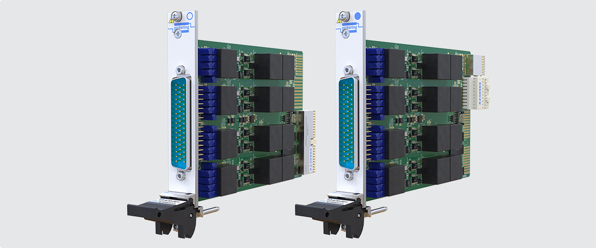
Figure 8 – Pickering Interfaces’ LVDT/RVDT/resolver simulator modules 41-670 (on the left) for PXI and 43-670 for PXIe (on the right).
They are the latest in our range of PXI/PXIe sensor and transducer simulation modules, including resistance temperature detector (RTD), thermocouple, strain-gauge and 4-20 mA current-loop simulators.
PXI and PXIe chassis with between eight and 21 slots are available from Pickering Interfaces. These chassis are fully compliant with the PXI standards and can house any vendor’s compliant modules.
Conclusion
LVDT, RVDT and resolvers are used in various applications, some of which are mission-critical. The simulation of these transducers dramatically simplifies and accelerates the development and test of closed-loop control systems – as well as systems primarily for measuring and monitoring – because it allows their full spectrum of functionality to be verified without needing real-world transducer hardware. Also, the versatility of Pickering Interfaces’ LVDT/RVDT/Resolver simulator is of use and value to the broad engineering community using one, both or all three transducer types.


