Configuring Pickering's PXI LVDT/RVDT/Resolver Simulator
Introduction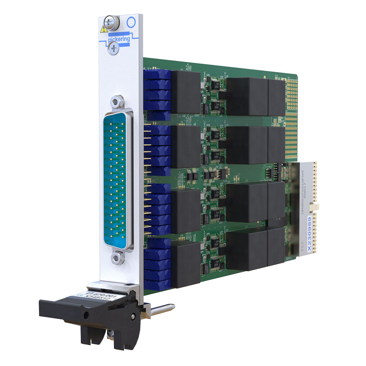
The implementation of VDT (Variable Differential Transformer) in configurations such as LVDT (Linear), RVDT (Rotational) or resolver is well understood by the electronics industry. However, there are likely a number of engineers who have never simulated a VDT when designing a test system for a device under test that monitors the response of these devices. Because there is a myriad of xVDT Devices on the market, with different parameters that need to be simulated, it can be a daunting task.
When purchasing the correct simulator for your application, there are many different selections, regardless of the manufacturer. This article will look at some of the considerations when configuring the Pickering's model 41-670 PXI LVDT, RVDT, Resolver Simulator module.
Bank
A bank is a pair of xVDT channels that can be used independently when simulating a 4-wire xVDT device or working as a single channel of 5-wire and 6-wire xVDT. Therefore, it is important to keep the terms Bank and Channel in the correct context.
VDT Specifications
As there are many different types of VDTs, the specifications (length of travel, rotation, linearity, Excitation frequency, etc.), are widely varied as well. It is important to know the specifications you will be simulating. Also important is to know what kind of tests does Engineering expect the system to perform? The key specifications to keep in mind are:
- Type of device to simulate – LVDT, RVDT or Resolver
- How many Channels?
- Configuration of LVDT and/or RVDT – 4-wire, 5-wire or 6-wire?
- Input Excitation Voltage
- Output Voltage
- Excitation Frequency
- Internal and/or External Excitation
- Fault Insertion
In addition, the requirements may be more than just simulating the output over the devices operating range. Other possible tests include Fault Insertion—what happened to the DUT if the input or output of the LVDT is shorted to each other or the cable breaks and opens the circuit? Do you need to simulate Interwinding and stray capacitances effects on output phase angle by adjusting output phase lag value? So be certain that you are aware of all of these requirements.
Selecting the correct model of the 41-670
- Simulation Modes - The model 41-670 can be ordered with either two or four banks of VDT simulation. Depending on your testing needs, the module can be ordered with LVDT/RVDT simulation, LVDT/RVDT/Resolver simulation, or Resolver simulation only. The latter has lesser functionality and is available at a lower cost than the other models.
- Input Voltage - The required Excitation Input voltage is an important parameter when selecting the correct model of the 41-670—there are five different Excitation voltage input ranges, and each module ordered only works at one of these ranges. The reason is that the inputs and outputs are transformer coupled for Galvanic isolation, and there is no one transformer that works across the entire voltage range supported by the 41-670 accurately. The table below shows the ranges.

Similarly, there are also five different output ranges, and each module supports only one of these ranges. The chart here shows the ranges.

Ordering the model 41-670
The following chart shows you how to configure the part number to get the correct configuration for your testing needs. If you need any assistance, please contact our Applications team at [email protected] or go to our contact us form here.