Contents
17 Oct 2023 • 11 minutes
Understanding Programmable Resistors for Sensor Simulation in Test
Learn how programmable resistors for sensor simulation drive test system optimization. This white paper details programmable resistor types, relay configurations, and specifications to help you design cost-effective, reliable hardware test solutions.
Introduction
If you think about it, sensors control much of our daily lives. Sensors ensure that the food in your refrigerator stays cold, count your steps on a smartphone, and even protects you in an automobile accident. So many devices in our personal lives as well as in business and other markets contain sensors.
All these sensors add a layer of complexity to your test strategy, as you need to simulate them when testing the circuit board that makes decisions based on a sensor’s response. Since it is usually not practical to incorporate actual sensors into a test fixture, Pickering Interfaces has created external hardware that is designed to replace these sensors in a test program. In this paper, we will talk about sensor simulation and how to select these products. With Pickering’s history of more than 15 years designing programmable resistors, we have the expertise and product depth to play an important role in testing sensor-driven products.
With Pickering’s history of more than 15 years designing programmable resistors, we have the expertise and product depth to play an important role in testing sensor-driven products.
What is a Programmable resistor?
As the name suggests, it is a resistor that is changed in value by a test program. The programmable resistor could be a device that plugs into a modular test format such as PXI. It can also be a stand-alone device controlled via USB or Ethernet.
For most programmable resistors, the values are changed using relays to short out a series of resistors. The relays could be reed relays, electro-mechanical relays, or solid-state relays. Each of these relay types has different relay chain advantages and disadvantages that we will touch on later.
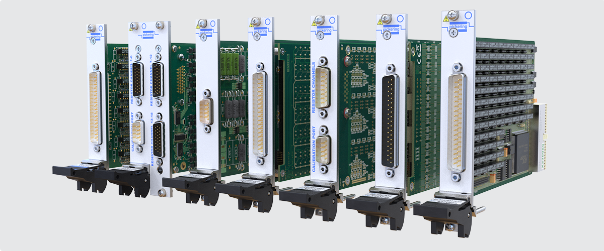
Examples of PXI Programmable Resistor Modules
There are many choices of programmable resistors in terms of range, power, accuracy, and resolution. Our goal here is to help you understand the differences and give guidance in selecting the correct programmable resistor for a given test application. As a portion of a test strategy, replacing actual sensors with simulation can lower costs by creating smaller test systems; for example, if you used actual temperature sensors in test, you will need a heat source to make the sensor react. A strain gauge will require a mechanical fixture that flexes a plate on which a strain gauge is mounted. Not only will the test system be much larger, chances are it will be slower when compared to using sensor simulation and less repeatable.
Markets and Technology Forces
The market for sensors is so large today you can be certain that if you are not testing products that incorporate sensors yet, you will be soon. It is estimated that the market for pressure sensors alone will be an almost $12 billion market by 2025 (Source: Grand View Research). The worldwide automotive sensor market, which incorporates most of the sensors mentioned earlier, will be a $36 billion market by 2023 (Source: Research and Markets). Such market estimates indicate that the technology will be around for quite some time and we need to test the controllers of these sensors.
With sensors in so many products, sensor simulation is likely to be part of your test strategy. As mentioned earlier, it is often not practical to use the end-product and the integrated sensors in this product as the test bed.
Programmable Resistor Types and Parameters
In figure 1, you see a PXI-based programmable resistor module (Pickering Interfaces’ model 40-295) based on relay chains. If we take a single channel, we see that it is composed of multiple resistors with individual relays connected across individual resistors. When all the relays are closed, the series resistance is effectively zero Ohms. In actuality, it can be a few hundred milliohms as each relay and the PCB itself will exhibit a very low resistance.
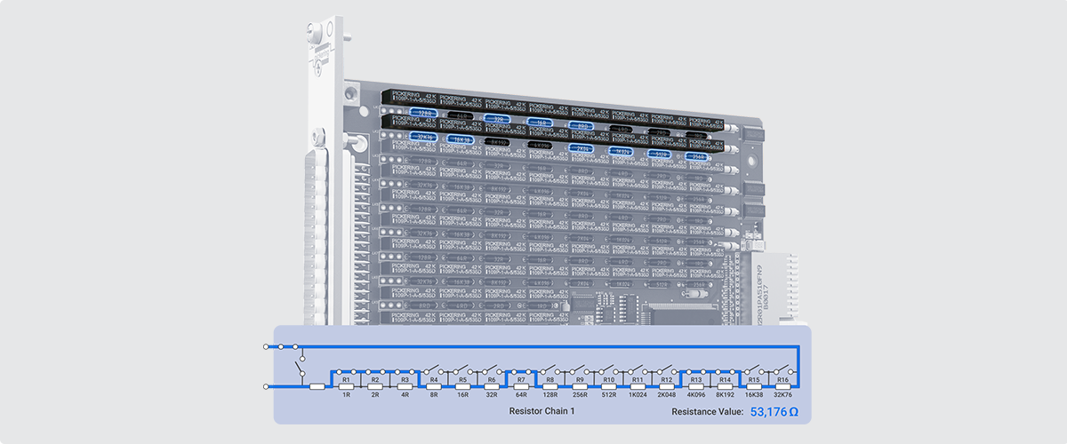
Figure 1 - Example Chain in a Programmable Resistor Module
As each relay is opened, the value of the resistor chain will equal the series resistance value of the resistors where the relay across one or more resistors is open. Resistor chain modules are available in 8-bit, 12- bit, 16-bit, and 24-bit. The larger the bit level of the resistor chain, the greater the resolution or range that can be achieved—the tradeoff is fewer channels on a module with higher bit resolution.
Need More Accuracy?
A precision programmable resistor module is designed to meet highly accurate test applications (figure 2 shows Pickering Interfaces’ model 40-262). The design is similar to the resistor chain mentioned above, as it does have a resistor chain for the coarse adjustments (see figure 3), with the addition of a digital potentiometer for fine adjustments. Using software that knows the value and accuracy of the resistor chain, the module can make fine adjustment settings to the channel being programmed. This configuration provides resistor settings orders of magnitude in terms of resolution and accuracy than standard resistor chains. The resolution on the precision resistor module is as low as 2 milliohms versus 250 milliohms on standard resistor chains and at an accuracy of 0.03% versus ±0.3% on standard resistor chains.
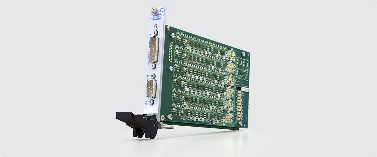
Figure 2 - Pickering 40-262 Precision Programmable Resistor Module
A precision resistor costs more than a standard resistor chain and may have fewer channels because of the added circuitry. But if the application demands this kind of accuracy, there are choices.

Figure 3 - One Channel of a Precision Programmable Resistor Module
Other configurations:
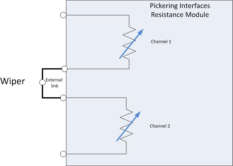
Some versions of programmable resistors include two relays per channel to inject faults into the test program. These relays can simulate a sensor short or an open.
Potentiometer simulation is created by connecting two resistor chains together, as shown in figure 4. Your test code should raise the value of one resistor chain and lower the other resistor chain’s value, just as a potentiometer works. You can also hard-wire two channels together.

Figure 4 - Programmable 40-282 Potential Divider Potentiometer Simulation
Finally, there are programmable resistor modules configured for a particular sensor type. The two most popular simulate an RTD (Resistive Temperature Detector) or the resistor bridge circuit in a strain gauge. These modules will have software drivers that allow you to set temperatures or program the value required to balance the bridge, and the setting of the simulator can be varied above and below this value to simulate extension and compression of a strain gauge (figure 5).
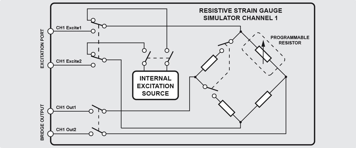
Figure 5 - Resistive Strain Gauge Simulator
Some additional features to look for are the ability to isolate a resistor channel or short the channel to present near-zero ohms to the device under test. This allows the program to inject faults into the test by simulating a bad connection to a sensor in the form of an open or short circuit.
If high-accuracy settings are required, look for resistor modules with a calibration port. In the schematic seen in figure 6, the calibration port is a multiplexer that switches the port to each channel, one at a time. Connecting a precision DMM to the port allows the user to verify the value of every setting required for their test program.

Figure 6 - RTD Simulator with Multiplexer and Calibration Port
Depending on the manufacturer and model, there is another feature that could be of benefit to you. Some programmable resistor modules feature uncommitted relays that can be used for several different reconfigurations of the resistor module. These include:
- Linking two resistor chains together, either in series or parallel, either extend the range of a resistor channel or improving its resolution.
- Adding additional bits to extend the range.
- Add a fixed resistor to be switched in to provide an offset resistance.
- Add additional fault conditions.
In a Modular Test platform, it is like having two modules in one chassis slot, which can free up a slot for additional instruments or switching.
Specifications Make the Simulation Just Right
Now that we have gone through all of the configuration options, you need to be aware of the properties of each resistor channel (see table 1 below for specifications of a typical resistor module).
| Accuracy: | ±0.2% ±Resolution @ ±10°C from calibration temperature (factory calibration @ 21°C) |
| Fault Simulation: | Open and short circuit (typically <0.3Ω) |
| Max Power: | 0.5W |
| Temperature Stability | 50ppm |
| Expected Life (operations): | 100 million (10mA) |
| Max Voltage: | 100V or as limited by power |
| Settling Time: | 3ms |
| Software Control: | By resistance calls to module for selected channel. |
Here are the considerations you need to keep in mind for resistor selection, though order of importance may vary depending on application:
- Programmable range – Initially, you need to know that maximum and minimum resistance meet the needs of your test requirements.
- Resolution – You’ll need to understand the minimum resolution of each channel. If your application requires higher resolution, your options with resistor chain designs are to either go to a higher bit configuration or parallel two or more channels together.
- Voltage and power – These are often forgotten until it may be too late. It is important to understand that the majority of resistor modules are limited to about half a watt at a max voltage of 100 volts.
- Accuracy – Remember that the accuracy is driven by the components used. As most accuracy specs are both plus and minus, you need to consider each setting or perhaps have a software driver that calculates the required value and sets the appropriate resistors and digital pots.
- Stability – Over a period of time, stability may be critical to your testing requirements. The resistors used will vary over a temperature range. As seen in table 1, the specifications note a stability of less than 50 parts per million.
- Number of channels – Selecting the number of channels required sounds like a simple decision; however, depending on your testing needs, there may be a balancing act. As mentioned earlier, higher-accuracy channels come at a price—higher accuracy usually requires more hardware, meaning that the module has fewer channels than you may require. It is recommended that you look at the accuracy and resolution needed for each sensor and select the type of modules that give you what is needed for your test program as well as saving slot count for other instruments.
- Relay types – The relays used in a programmable resistor channel have an influence on how the resistor channel performs; therefore, you many need to factor in relay types depending on your requirements.

Below is an explanation of each type of relay that can be used in a programmable resistor:
| Electro-mechanical relays or EMRs – These are the lowest-cost relays. In some instances, EMRs can cost as much as 30% lower when compared to an equivalent reed relay. EMRs have a very low thermal EMF – typically less than 3 μv – which can be important in very low-level signals. The downside of EMRs is that they are the slowest in terms of switching times, typically rated in milliseconds. They also have the shortest life span of relays, roughly >2x10⁷ operations at low-power switching. |

|
|
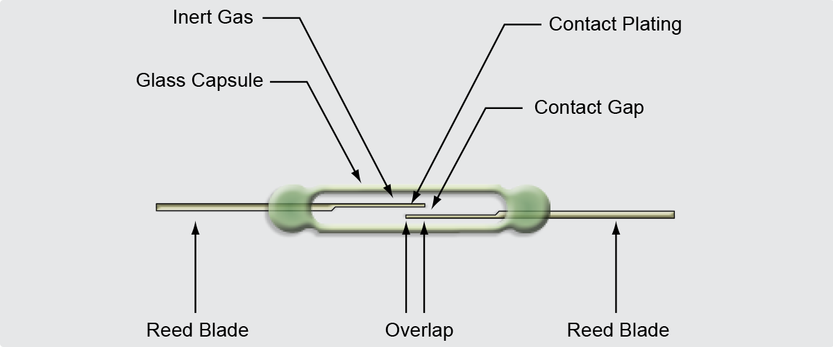
Reed relays – These relays have the fastest switching time of any mechanical relay, typically 500 μ seconds or less. Also, reed relays will exhibit an average life of 1x10⁹ operations. This does come at a higher cost than EMRs and they have a moderately higher thermal EMF (Typically, less than 5 μV). |
Solid-state relays – These relays have the fastest switching times, typically 200 ns and no switch bounce, providing a more stable environment. In practice, if the test program stays within the specifications of the module, the module will not wear out. The downside is that there is relatively high leakage and a lower isolation resistance. These factors can make solid-state switching unusable in certain applications.
Control Method
Now that you have chosen the parameters required for the test, how are you going to control it? Depending on the module type, there are choices:
- Bit-level control – For a resistor chain, the simplest way is to program the resistor module at the bit level where you close individual relays to create the resistor value you require. If you are using a lot of resistor channels, this can be cumbersome.
- Resistance calls – Many manufacturers will provide software drivers that allow you to specify the resistance required in your test code and the driver will make the appropriate relay closures.
- Soft front panel – A soft front panel is ideal for debugging, as it allows you to vary the resistance without writing code.
- Special functions – There are special function calls for special functions like temperature or strain bridges; the calls should be intuitive in order make your job easier.
- Number of operations – In our experience, we have customers that are using Pickering programmable resistor modules in a high-volume environment, running two and even three shifts daily. At that rate, the modules will wear out in several years or less. Make sure to review your test program to see how many times the resistor channels are exercised as well as daily tester throughput. Then you can see if you need to plan a replacement program sometime in the future.
- Resistor damage – All resistor modules have specifications indicating maximum voltage and power dissipation. Exceeding either of these specifications can cause the resistor to overheat and change its value.
- Hot switching – This is a test technique that switches relays while power is applied. Depending on how much power is switched, hot switching can greatly reduce the life of the relays in the resistor chain. If possible, try to cold switch – in other words, set the values with the power turned off and apply power after the relays are in the correct state.
“Care and Feeding” of Resistor Channels
As programmable resistor channels use relay and resistors, it is possible to damage the module if certain guidelines are not followed. Below are a couple of points to keep in mind:
|
|
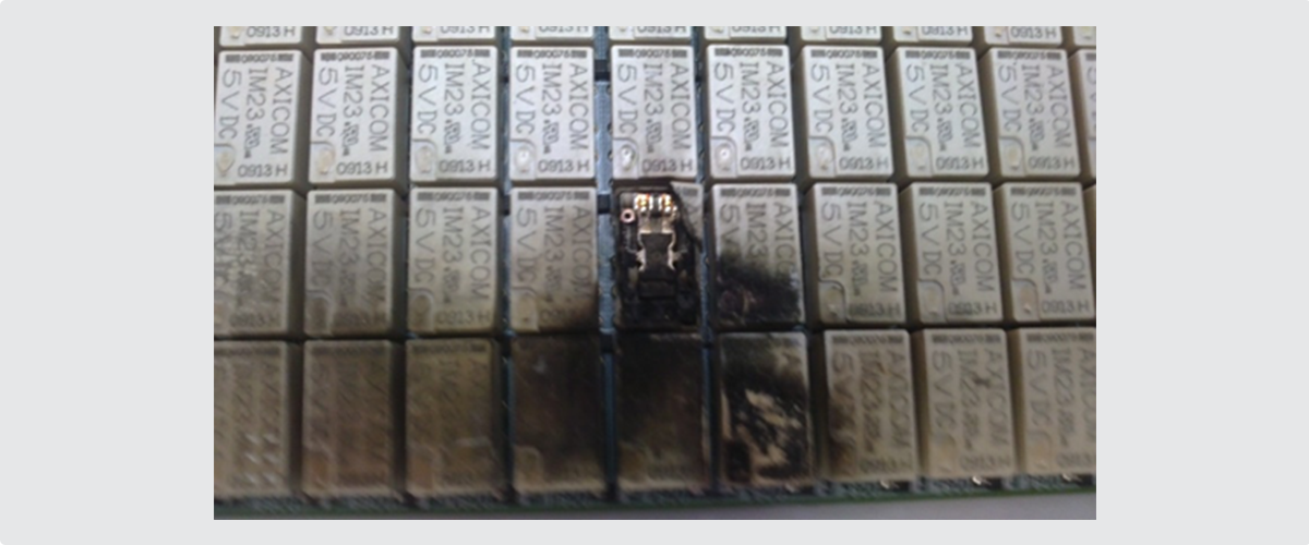
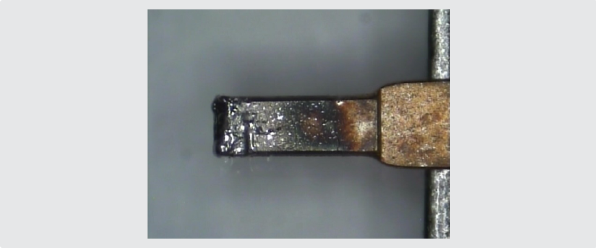
| Figure 7 - Module Damage Caused by Overload | Figure 8 - Relay Contact Damage |
If your test code and applications do not always follow these guidelines, what are the symptoms? They can include low or high resistor values, intermittent settings, and even offset voltages not planned for. Worst case: you may end up with burnt contacts or even a burnt module.
It is best to keep in mind the module’s parameters and evaluate your test code.
Conclusion
As you can see, there are many things to consider when selecting programmable resistor modules. It is undeniable that sensors are in virtually every application for electronics, making testing important, and sensor simulation can help you get there.
Fortunately, Pickering Interfaces has the broadest range of programmable resistors available in both PXI and PCI formats. From standard resistor chains to precision resistors to specialized modules, chances are that Pickering has sensor simulations for your applications.
To help you in your selection, we have additional resources on our web site, including articles and videos on programmable resistors, in addition to success stories from our customers on how programmable resistors made their test systems more comprehensive and accurate.
We hope you have gained some valuable knowledge for your test strategies. Please contact one of our sales offices where you can learn more about selecting and using programmable resistors as well as see the choices provided by Pickering Interfaces.