
Saving Significant Costs & Time: Accelerating Automotive ECU Testing Efficiency
Pickering Interfaces helps an automotive customer save tens of thousands of dollars on ATE systems for testing multiple ECUs.
In the automotive sector, functional testing is an essential aspect of product development and a means of quality assurance during volume production. Testing comes at a cost, though—one that must be kept as low as possible without compromising the depth of test or value of the data collected. For original equipment manufacturers (OEMs), making informed decisions when designing or acquiring automated test equipment (ATE) is essential. The ATE must deliver the required tests with speed and precision, ensuring efficiency without compromising accuracy. Since ATE represents a non-recurring engineering (NRE) cost, its affordability plays a critical role in the decision-making process.
However, it is equally important that if a more efficient and cost-effective solution presents itself, the OEM should be prepared to take that alternative route, as this can save significant time and money.
Taking the alternative route is precisely what one of Pickering Interface’s customers recently did, and it paid off—they saved tens of thousands of euros and greatly increased the speed of their tests.
The Challenge
The customer in question had a requirement to automatically measure the voltages of 256 analog outputs of an electronic control unit (ECU) being manufactured. They also needed to determine that when each output was high (approx. 16 V), the voltage was above a specified threshold, and when low (approx. 0 V), the voltage was below a different threshold. Moreover, the company wanted to be able to test three ECUs at once, and accordingly, their automatic test equipment (ATE) would need at least 768 measurement channels. The test system would also need to interface to the customer’s in-house CANoe ECU development and testing software tool from Vector Informatik GmbH.
The OEM’s initial proposal was to replicate their existing single ECU test system (see Figure 1 below). This was from an incumbent supplier and used four interconnected 72-channel multiplexer cards housed in an Ethernet-controlled 2U chassis, together with an integral DMM. Each of the 256 ECU outputs was switched one at a time to the DMM, the voltage measured, and the result sent over the local network via a custom S/W driver to a PC running CANoe. There, the readings were compared against the required upper and lower voltage thresholds, and a pass or fail was recorded for the ECU.

Figure 1: The customer's existing single ECU test system configuration.

Figure 2 - The customer’s new strategy was to test three ECUs simultaneously, so the original four multiplexer cards would need to be triplicated in the final ATE.
As production volumes increased, multiple identical test systems would be needed. These requirements drove the customer to investigate whether a smaller, lower-cost, and faster test-time solution could be found.
Our Approach
We initially met with the customer to explore whether we could formulate a more effective alternative test philosophy. Two main areas of improvement were identified:
- The original test system was relatively slow due to each ECU output's serial switching/measurement/computation—the three-up ECU test would take three times as long.
- It was also quite large and costly, as 12 interconnected multiplexer cards would be needed to handle the three-up testers’ required 768 channels. However, each 2U chassis could only accommodate six cards, so two chassis would be required per test system.
We presented our 40-412-111 32-channel PXI Digital I/O module (see Figure 3) as a potential solution. The states of the 32 input channels are read via the PXI interface by comparing the input levels to two threshold voltages. These can be set between 0.3V and 50V and have a resolution of 12.5mV. This allows the input to be tested against system limits, defining a low or high logic level.
The module also features parallel acquisition using 32 sets of comparators to synchronously capture all 32 input states and
read them in a single operation, significantly reducing test time. Additionally, the modules can be used in our LXI chassis, offering a compact format and mirroring the simple Ethernet control of their existing solution.
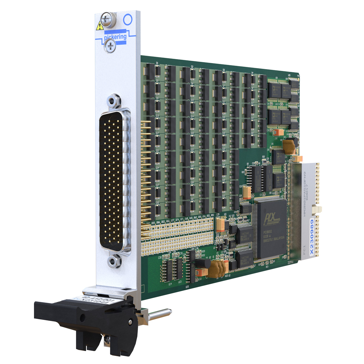
Figure 3 - The 40-412-111 is a PXI 32-channel digital I/O module with dual programmable input thresholds and parallel input acquisition.
The customer expressed significant interest in this approach, as it could lead to a smaller, faster, lower-cost solution. However, the module was not ideally suited to their application, as they did not need the 32 output channels on each module.
We had always planned to expand our DIO module range with other digital input and output configurations, and we saw this as an ideal opportunity to produce a high-density digital input module.
In the meantime, the OEM was loaned four 40-412-111 modules (enough to provide 128 channels, sufficient for testing a single ECU), an LXI chassis, and custom cabling. CANoe drivers were also supplied to allow it to operate with their existing framework.
This enabled the OEM to build a demo ATE and successfully prove the feasibility of this alternative solution. As expected, the tests were significantly faster than before, thanks to the direct voltage threshold testing capability of our DIO modules.
The Solution
Meanwhile, Pickering’s engineering team developed the 40/42-414 PXI/PXIe high-density digital input module family (see Figure 4), all with 128 input channels. Like the 32-channel digital I/O card, dual input thresholds can be programmed, but now with support for voltages up to 300 V, depending on the selected variant. Unlike the 40-412 module, which applies the same thresholds across all input channels, the new modules offer greater flexibility by allowing thresholds to be configured in banks of eight channels each.
Figure 4—The new 40-414 (PXI) and 42-414 (PXIe) families are 128-channel digital input modules, with variants having 50V, 100V, 200V, and 300V input voltage ranges. Dual programmable input threshold voltages offer an efficient method for assessing the status of input lines, enabling rapid identification of whether the input is low, high, or indeterminate.
The final test system configuration, using the new 128-channel modules, is shown in Figure 5 below.

Figure 5 - Final three-up ECU test system configuration
Once the new modules were available, the customer immediately ordered 42, enough for seven three-up ATEs, together with six custom cables per system for interconnecting the ECUs and DIO modules. Each system’s modules were housed in our rack-mount 60-106 1U 6-slot LXI/USB chassis (see Figure 6), providing an extremely space-efficient solution.
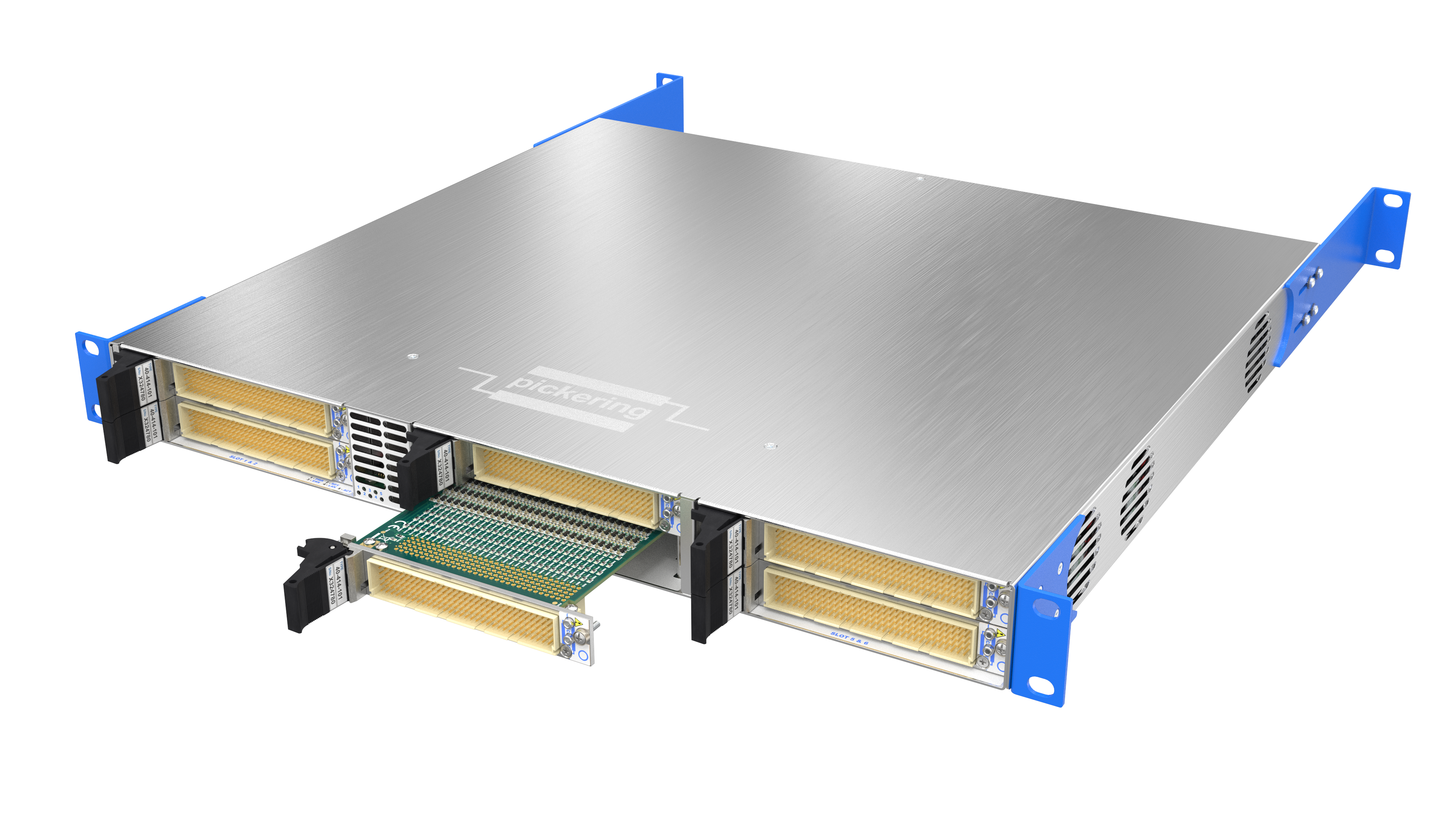
Figure 6 – The final test system configuration is our 60-106 1U LXI/USB chassis which can accommodate up to six Pickering PXI modules.
Ultimately, we supplied:
- Six – LXI/USB 4-slot chassis (model 60-105)
- Three – LXI/USB 6-slot chassis (model 60-106)
- 42 – 128-channel digital input PXI modules (model 40-414)
In Summary
The Pickering solution offers significant advantages over the incumbent option. It eliminates the need for multiple multiplexers during testing, resulting in cost savings. Additionally, using higher-density modules reduces the number of modules required, allowing for smaller and more affordable chassis, and minimizing the need for extensive cabling—further lowering costs. Pickering's standard CANoe driver removed the need for the OEM to create a custom driver for the new testing solution. Combined, these enhancements are projected to save the OEM tens of thousands of euros.
Replacing the previous per-channel serial sequences of switching, measurement (including DMM settling time), and remote PC computation with direct parallel threshold comparisons in our DIO modules reduced test time by a factor of 10. Without such a high throughput, additional ATEs would have been needed if the OEM had stuck with and expanded its original solution. Again, money is saved.


