Accelerating Large-scale Semiconductor Parametric Testing Using a Multi-bus Switch Matrix
Time-to-market of new, innovative product designs is critical in the fast-moving, competitive semiconductor industry. But
with suppliers’ brand reputations at stake, extensive testing must be performed during the device development phase to ensure
the long-term reliability of every aspect of their products, which need to function consistently in a vast array of challenging
customer environments.

With the total number of DUT pins potentially running into hundreds or even thousands when testing, for example, the latest
server CPU packages, a high pin-count automated switching system is required to quickly and reliably connect the SMU sequentially
across pairs of DUT pins for each parametric test, —with two individual test connections needed on every pin for the 4-wire
measurements.
Reliability validation can be a lengthy process based on Highly Accelerated Stress Testing, whereby the semiconductor device
under test (DUT) is cycled through environmental extremes of temperature, humidity, and mechanical stress. The goal is
to cause the device to fail—the failure mechanism can then be investigated—and any potential problems rectified.
During or following each applied stress cycle, the DUT typically undergoes some form of parametric testing, which involves
the electrical testing and characterization of dedicated test structures manufactured on the semiconductor wafer or package
substrate to verify whether the specific structures still satisfy the required design criteria. These tests are typically
performed by a Source/Measurement Unit (SMU) and range from simple resistance measurements to scanned current versus
voltage (IV) or capacitance versus voltage (CV) measurements, usually made via Kelvin 4-wire connections to eliminate
instrument-to-DUT interconnection resistance, as illustrated in Fig.1
Fig.1 Kelvin 4-terminal resistance measurement configuration
With IC designers constantly striving to accelerate reliability testing without compromising quality, a parametric test system
must be designed to minimize the test time for this large number of DUT pins. One relatively straightforward way
of achieving this goal is to connect two SMUs in parallel to different pairs of DUT pins and record their parametric
measurements simultaneously, effectively halving the overall test time. Building upon this strategy, Pickering has worked
closely with leading semiconductor manufacturers to produce a high pin-count switch matrix platform specifically optimized
for very fast, 4-wire parametric testing by simultaneously connecting up to 12 SMUs to the DUT in parallel.
Pickering modular switch matrix platform
The 65-221 is a modular switching system
designed to provide a high-density scalable matrix solution, as shown in Fig 2.

Fig.2 65-221 LXI modular chassis fitted with six plug-in matrix modules.
It comprises an industry-standard LXI-compliant, Ethernet-controlled modular chassis (65-200-002) in a compact 2U rack-mount
enclosure. The chassis can host up to six plug-in matrix modules, each configured with dual 128x4 sub-matrices utilizing Pickering
instrumentation-grade reed relays for long service life and excellent low-level signal switching performance, with maximum
signal handling of 1 A and 150 VDC. Users can specify the number of plug-in modules required for their DUT size and field
upgrade the chassis to expand the matrix if necessary.

Fig.3 65-221 overview schematic
Large-scale Parallel Parametric Testing
The 12 4-wire analog buses enable highly parallel parametric testing applications using up to 12 SMUs simultaneously.
Each of the four connections from each SMU can be routed via an analog bus to a Y-bus line of any of the 12 individual
128x4 sub-matrices across the six plug-in modules and can thereby be connected to any DUT pin. Fig.4 shows one specific
example of this: each SMU is connected to an individual sub-matrix and used to measure the resistance between adjacent
DUT pins.
The 12 SMUs make their 4-wire parametric measurements simultaneously. Then, each submatrix’s X connections are incremented to the next set of two DUT pins, and the process is repeated for up to 32 resistance measurements per SMU (128 submatrix X connections divided by 4), e.g., a total of 384 measurements across the six plugins.
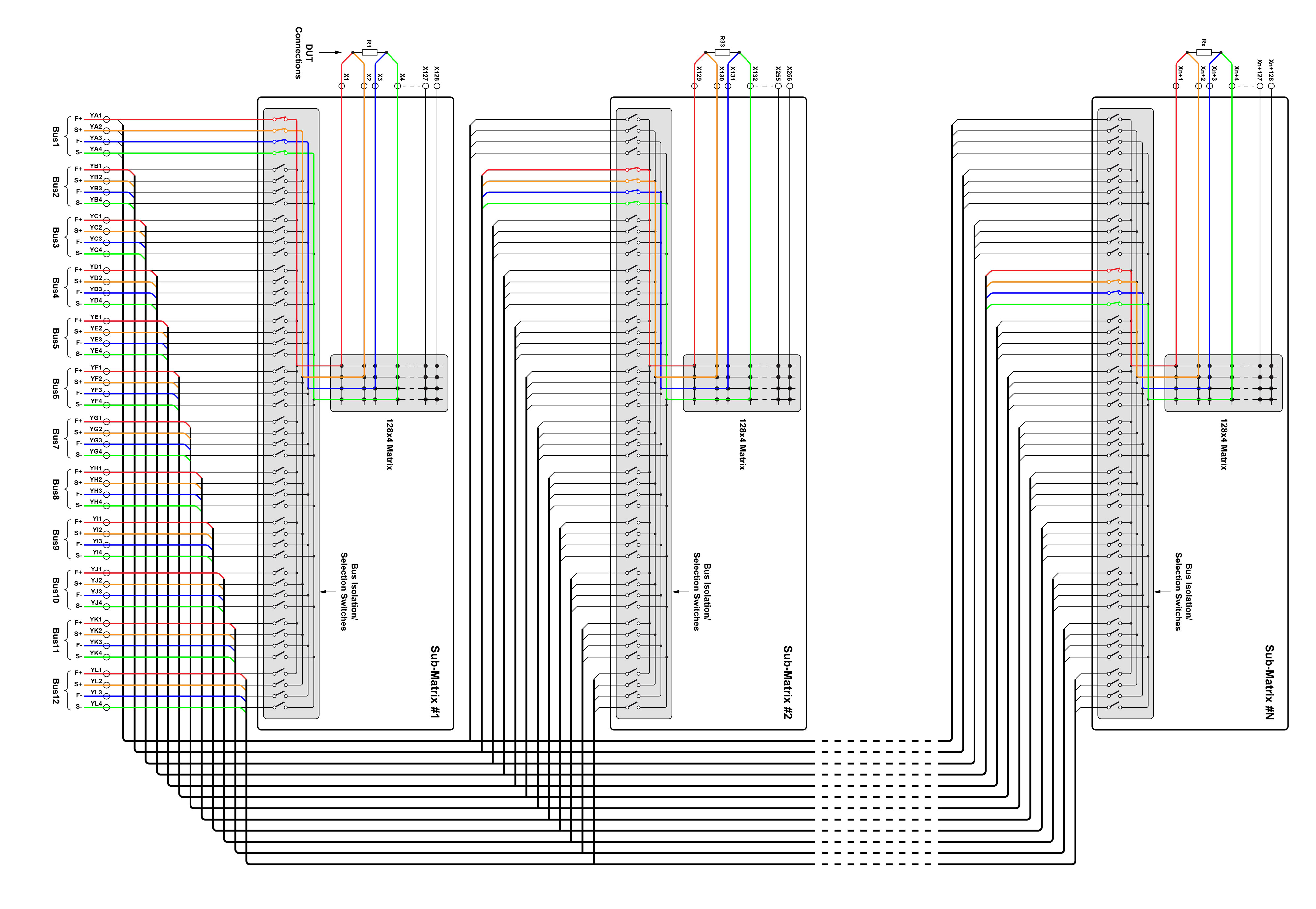
Fig.4 65-221 Configured as twelve individual 128x4 matrices for parallel parametric testing
Scan-list Sequencing and Triggering
To optimize the speed of this measurement loop, the 65-221 chassis is equipped with a scan-list sequencing service, whereby
a sequence of switch settings for all individual measurements is loaded into the chassis controller firmware, and the
sequence is initiated by a hardware “ready” trigger from one of the SMUs which has been designated as the master instrument.
When the required switch settings have been made, the chassis returns a “ready” trigger to the master, which then requests
all SMUs to make and record their parametric measurements in onboard memory. Once it has received “measurement complete”
signals from every instrument, the master sends a “ready” trigger to the matrix, which then actions the next switch settings
in the scan list and the process is repeated. All stored SMU measurements can then be analyzed.
As the switch state sequences are stored within the LXI controller, the burden on the Host CPU and Ethernet traffic
is significantly reduced, resulting in reduced overall system latency.
Application Flexibility
If the DUT requires more than 1536 test connections, one or more 65-221 matrix systems can easily be added by
daisy-chaining the 12 4-wire buses between each unit. Pickering’s Connect division offers standard or custom cable assemblies and can manufacture the required cabling. To simplify the programming of
these complex switching systems, Pickering’s Switch Path Manager automated signal routing application may be used to
resolve the required multiple relay operations down to a single endpoint-to-endpoint command such as CONNECT
(SMU7_HI, DUT_274).
If the application needs fewer SMUs, a lower cost 65-221 plug-in variant is available with provision for up to six SMUs instead
of 12. To address a range of differing DUT applications, Pickering has developed three other variants of matrix plug-ins
with differing quantities of Y-axis signals and analog buses, namely six buses / eight signals wide, three buses / 16 signals,
and one bus / 32 signals (model numbers 65-223, -225 and -227 respectively), all utilizing the same 65-200-002 chassis
as the 65-221.
Maintainability
The Pickering reed relays fitted to the matrix are extremely reliable under normal operating conditions. Still, being mechanical
components, they have mechanical endurance and could fail if subjected to signals exceeding their maximum operating
specifications. As the matrix is at the heart of the parametric testing system, any downtime due to a relay failure can
seriously impact the whole reliability testing program. The 65-221 has been designed from the ground up to address this potential issue to minimize mean-time-to-repair (MTTR). Each 128x4 sub-matrix of the plug-in modules comprises
four 32x4 plug-on matrix modules that connect to the plug-in via high-reliability sockets, as shown in Fig.5.
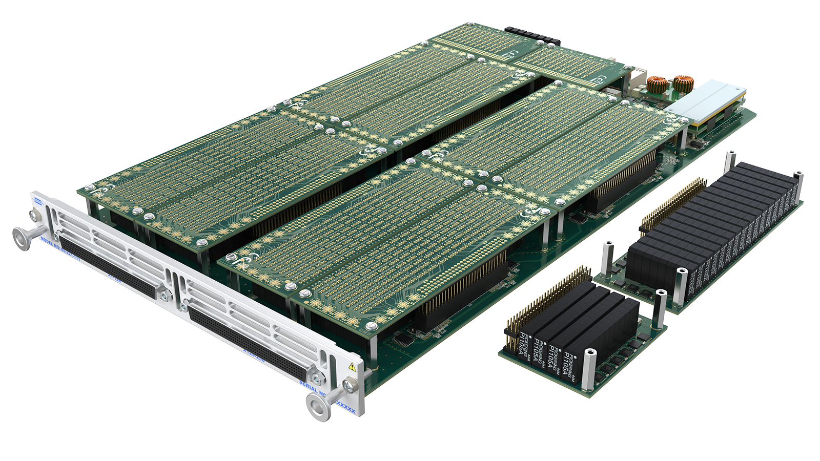
Fig. 5. 65-221 sub-matrix plug-in showing the easily replaceable plug-on modules.
The isolation relays that connect the analog buses to each sub-matrix are also on similar plug-ons. If a relay failure is
suspected, Pickering supplies two diagnostic test tools that may be used to find the faulty relay. The 65-221 has an
integrated BIRST (Built-In Relay Self-Test) tool that can diagnose a failure to a specific plug-in and, in many instances, down to an individual plug-on module. If spares are held, the faulty module may be replaced with a known good spare.
The matrix can then be reassembled, retested and quickly returned to service. At a scheduled maintenance session, any
faulty plug-ons may be refitted to the chassis and tested by Pickering’s eBIRST application. This uses two external USB-controlled
test tools that are connected between each plug-in and quickly and accurately test the functionality of every relay –
see Fig. 6. Any indicted relay can be easily removed and replaced - all are through-hole, and spare relays are included
on every plugin. The repaired plug-on is then retested and returned to spares inventory for future use.

Fig.6 Using an eBIRST Diagnostic Test Tool system to test a 65-221 LXI switch unit.
Summary
Parametric testing is essential to semiconductor device reliability testing but can be a lengthy process for high-pin-count
devices. To help semiconductor manufacturers accelerate their time to market for new product designs, Pickering has developed
a high-speed, low MTTR flexible switch matrix platform that facilitates large-scale parallel parametric testing and can
help significantly reduce device validation cycle times.
Learn more about our semiconductor test solutions here