


DMC used Pickering Interfaces' monitored multiplexer modules to help automate the breakout-box (BOB) function in the ground support test equipment developed for NASA's Space Launch System (SLS) Booster Obsolescence Life Extension (BOLE) program.
The Customer and the Challenge
Established in 1996 and operating across multiple sites in the USA, DMC is a project-based engineering firm that develops and implements solutions for a wide range of industries. In 2023, Northrop Grumman selected DMC to build a test system for NASA's SLS BOLE program, which develops next-generation, five-segment solid rocket boosters to replace the retired Space Shuttle-era steel cases.
As part of the contract, DMC was responsible for creating automated ground support test equipment to help qualify each booster for NASA's Artemis missions.
The SLS booster contains multiple, different line-replaceable units (LRUs), located in avionics racks in the rocket's aft and forward skirts (see Figure 1). Among other tasks, these LRUs control the stage, take measurements, and communicate with the rest of the vehicle.
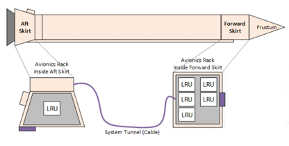
Figure 1 - The test system DMC, designed to replicate the booster's architecture, uses bare avionics racks (one of which sits in a remote lab) and the same cable types and lengths used on the platform. In effect, it operates much like an iron bird test rig.
What Is a Breakout Box, and Why Automate It?
Most test systems used in the development, test, and certification of avionics include BOBs, which are inserted in line between an LRU and its associated sensors, actuators, and communication devices, and intercept and surface the signals passing between them.
Each signal has its own accessible test point, typically two banana sockets and a short jack lead, that lets an engineer measure and monitor that signal. It is also common practice to inject faults through the BOB to see how the system responds. For example, pulling the banana jack lead on a given signal creates an open circuit.
A traditional BOB is entirely manual, requiring an engineer to physically connect instruments, take each measurement by hand, record the results, and manually insert faults. On a system with hundreds of signals, this approach is slow, difficult to repeat consistently, and prone to human error.
The goal of the BOLE program was to remove that manual intervention. As Zak Pearson, Senior Project Engineer at DMC, explained: A key aspect of the BOLE program was that the BOLE test rig's BOBs should be automated as much as possible to provide high levels of repeatability, make data recording easier, and remove human error.
The AutoBOB: Adding Programmable Switching
To achieve this, DMC designed an automated breakout box (AutoBOB) for each LRU type in the booster's avionics system. The AutoBOB retains all the functions of a traditional BOB but replaces manual intervention with programmable switching. Specifically, each AutoBOB contains a multiplexer, which allows signals to be tapped and routed under software control rather than by hand.
Within a typical AutoBOB signal line, a single signal passes through a shunt resistor, a fault insertion relay, and a banana jack jumper, with three tap points in the circuit. (see Figure 2).
A Pickering-monitored multiplexer card (40-619-002) selects which signals to route, and a Pickering relay driver module (40-411-001) drives the fault-insertion relays.
Most signals are tapped and channeled to a main rack containing test and measurement instruments.
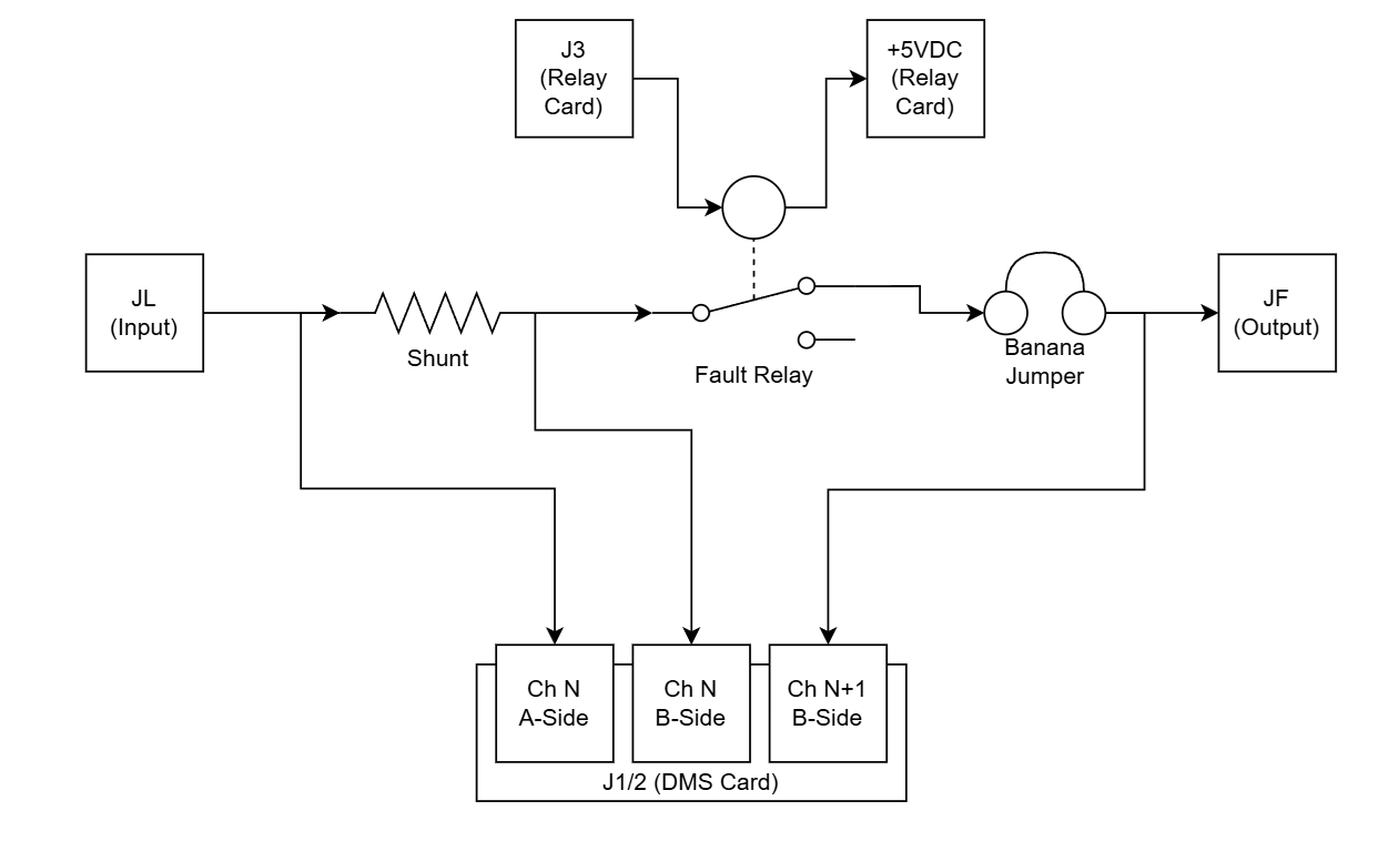
Figure 2. Above, an example of a single signal line passing through a shunt resistor, a fault insertion relay, and a banana jack jumper. There are three tap points within the circuit, all connected to the Pickering monitored multiplexer. A current measurement would, for example, be taken (or rather calculated) by measuring the voltage drop across the shunt resistor.
Monitored Switching: Verifying Relay State
Above, a key word to focus on is ‘monitored’. On a standard multiplexer, when any given relay is commanded to operate, there is no feedback to the controller confirming the operation was successful. A relay could be stuck open or closed; the latter being particularly dangerous as it can cause a short circuit, exactly the kind of unintended fault condition an AutoBOB should never introduce.
Pickering addressed this problem by developing specialized monitored multiplexer modules. These provide monitoring points that allow a resistance-measurement instrument to be connected across a relay to verify that it is in the correct state. Each relay resides on a high-density multiplexer module inside the AutoBOB, and its state can be confirmed before a test proceeds.
Note: This monitoring capability was developed specifically for a customer design review (CDR) and helped DMC secure its contract with Northrop Grumman.
The system as a whole is very advanced, and the monitored multiplexers are particularly clever, Pearson continued. We have positive feedback that the relay has physically operated, and that gives us confidence in the test results. Also, by overseeing the relay operation, we can make sure signals are not accidentally shorted, which is important when you're dealing with power buses.
The Test System
Almost every signal to and from an LRU passes through an accompanying AutoBOB, with signal counts ranging from 12 to 112. Signal types within the system include analog voltages and currents, digital I/O, and communication buses (MIL-STD-1553B and RS-422).
As mentioned, an AutoBOB’s multiplexer can connect to any signal at the various tap points. However, the multiplexer is not allowed to complete the circuit (from the LRU side to the cable side) for the signal. For low-current signals, a PCB completes the circuit, while high-current signals (some exceeding 30A) have their circuit completed by wires and terminal blocks.
In addition to the multiplexer cards inside the AutoBOBs, a Pickering PXI high-density matrix (40-576-001) sits in the main rack (see Figure 3) within the Electrical Production Support Equipment (EPSE – see Figure 4).
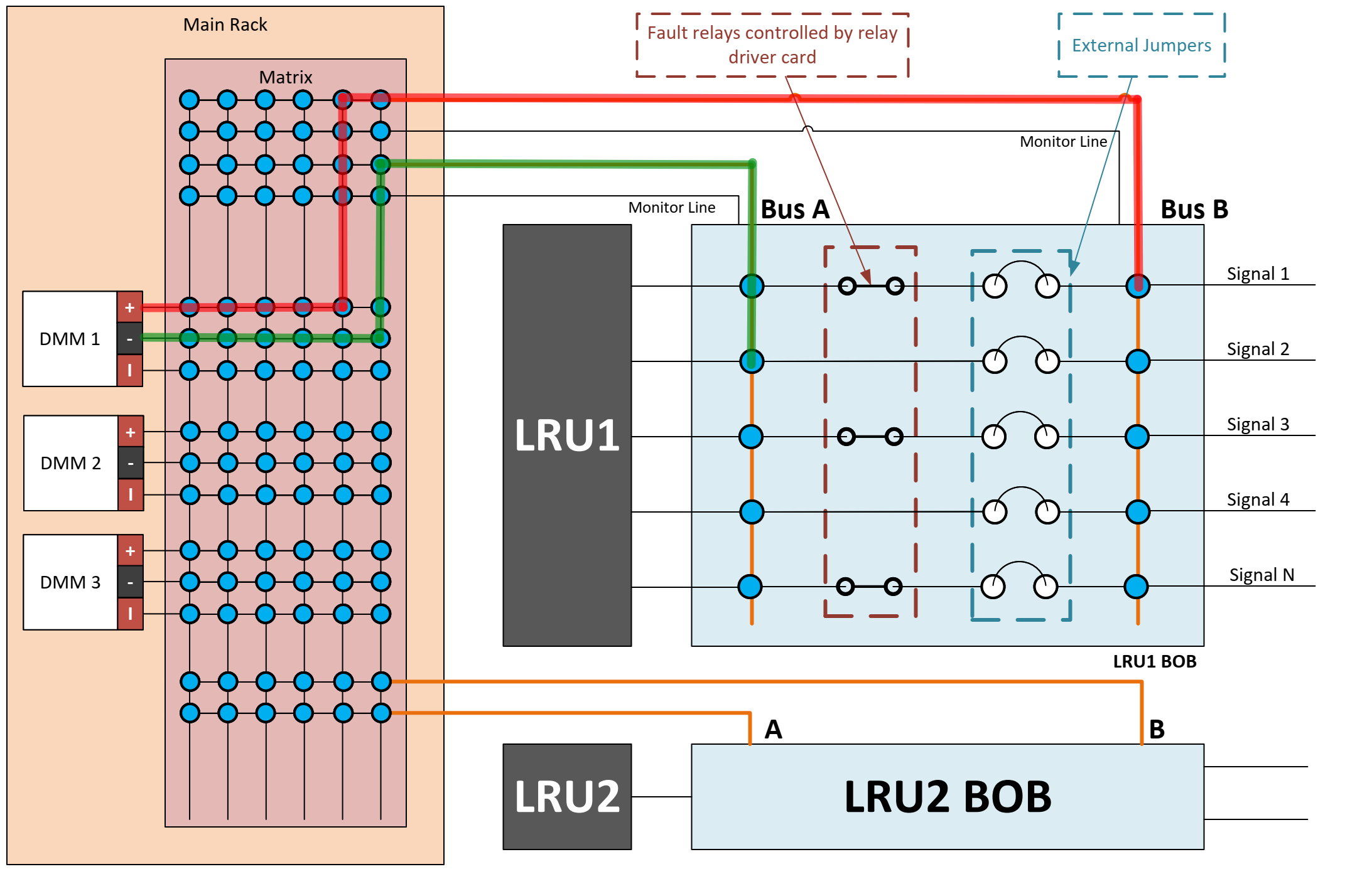
Figure 3. On the left, the matrix in the main rack (EPSE) connects instruments (in this case DMMs, but it also contains oscilloscopes and other instruments) to the AutoBOBs. On the right, the multiplexer cards within the AutoBOBs select which signals to tap into and send to the main rack matrix. The highlighted (red and green) paths show a sample measurement; DMM1 is measuring the voltage (or resistance) between LRU1’s signals 1 and 2.
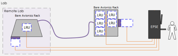
Figure 4. The AutoBOBs are mounted inside the avionics racks, next to the LRUs, and all signals route back to the main rack (the EPSE). The cables connecting each AutoBOB to the main rack can be up to 60m long, and DMC used Pickering’s multiplexers to automatically compensate for line resistance.
The main rack matrix connects instruments (digital multimeters, oscilloscopes, and others) to the AutoBOBs, while the multiplexer cards within the AutoBOBs select which signals to tap and send to the main rack matrix.
The AutoBOBs mount inside the avionics racks, next to the LRUs, and all signals route back to the main rack (the EPSE). The cable connecting each AutoBOB to the main rack can run up to 60m long, so DMC used Pickering's multiplexers to automatically compensate for line resistance.
Capable and Versatile
To simplify connection to the main instrumentation rack, all AutoBOBs use identical, standardized connectors that allow easy swapping. When the system software initializes, the AutoBOBs run an automatic identification routine to assign themselves to the correct slots, thereby easing tracking of redundant LRU buses. Any AutoBOB intended for a given LRU type can be plugged into its slot, and the software identifies it and tracks the data accordingly.
Once installed between the flight cables and the LRU, an AutoBOB can be commanded to tap into signals and direct them to the EPSE, or to introduce open circuits. Green and yellow banana jack jumpers surface signals so engineers can still take manual measurements and introduce open-circuit faults, exactly as they would with a traditional BOB.
Pearson added that the AutoBOB's manual capabilities provide important redundancy. If an AutoBOB is simply placed in line and not controlled or powered, it acts like a traditional BOB.
The system DMC developed, along with the AutoBOBs and EPSE, featuring Pickering’s monitored multiplexers and relay driver modules (for fault insertions), has greatly reduced the time required for test equipment calibration. This calibration takes place before and after each test campaign to record how the equipment performed and to help ensure the validity of test results.
In the past, this process was entirely manual and involved several steps, including continuity and isolation checks to confirm there were no inadvertent open or short circuits before power-up. These checks could take weeks to complete.
Pearson concludes: The AutoBOBs have not only enabled the automation of these many checks and saved a great deal of time, but they also remove the risk of human error, thus giving higher confidence in the thorough calibration of the equipment and the results obtained during the customer's test campaigns.
Maximizing System Uptime
While the system is robust and versatile, its automated operation and extended test times mean that if a monitored multiplexer indicates a potential relay problem, it is imperative to diagnose and repair the module promptly.
In this respect, Pickering’s built-in relay self-test (eBIRST) diagnostic tools can automatically pinpoint faults in the switch system by measuring signal-path resistance with an accurate four-wire measurement technique. This enables field engineers to quickly determine which relays have failed and whether any have increased contact resistance, which would indicate they are approaching end of life. This significantly reduces mean time to repair (MTTR) and maximizes system uptime.
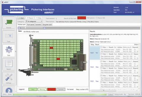
Figure 5. eBIRST flags warnings for relays with increased contact resistance and highlights shorted and stuck-open devices. (Note: the above screenshot is for illustrative purposes only and not related to the project being discussed here.)
Summary
DMC designed and built the AutoBOBs for the development, test, and certification of the booster's LRUs on NASA's SLS BOLE program; you can read DMC’s full story here.
Pickering Interfaces greatly supported this project by modifying existing switching products, most notably by adding monitoring capability, to enable DMC to verify relay states and automate the BOB function without risk of introducing unintended faults.
Controlled from a main rack, the AutoBOBs intercept signals, introduce faults on command, improve repeatability, and remove human error, while retaining full manual capability for redundancy.
The monitored multiplexer solution Pickering devised for this project has since been standardized and added to the company's product portfolio as the 40–619 series of high-density PXI monitored multiplexer switch modules.
Explore Rocket & Space Testing Solutions
Discover how Pickering Interfaces' modular switching, simulation, and instrumentation solutions help engineers develop reliable, flexible test systems for rocket, spacecraft, and aerospace applications.


