
Contents
01 Oct 2021 • 7 - 9 minutes
Using PXI-based Fault Insertion & Sensor Simulation in Electronic Test
Discover how modular test architectures help manufacturers reduce NRE costs, eliminate redundant engineering, and scale functional testing from prototype development to high-volume production using Bloomy's UTS platforms and Pickering switching technology
Introduction
Electronic Control Units (ECUs) are present in many applications today, often used in mission- and safety-critical situations that demand not only high reliability, but also high operational predictability. The correct operation of these ECUs is typically verified by using Hardware in the Loop Simulation (HILS), which replaces the sensors that monitor the ECU’s real-world environment by electronic simulators. Fault insertion is also commonly used in HILS systems to ensure the ECU operates safely and reliably under all possible good and bad operating conditions, and with ever increasing ECU complexity, it is essential to automate this fault testing to keep the validation process quick and repeatable. This White Paper will discuss the benefits of using the industry standard PXI platform for HILS automated fault insertion and sensor simulation.
The job of an airplane test pilot used to be extremely dangerous. The only way a design could be thoroughly evaluated was when a working prototype was flown for the first time. Even when an aircraft was deemed flight-worthy and entered production, the combination of many related or unrelated faults or circumstances could cause unpredictable aircraft behavior, resulting in planes crashing. In space, equipment failures are even more challenging to resolve.
As ECUs find their way more and more into cars and aerospace applications, the need for operational reliability and predictability is perhaps even more significant considering the number of vehicles there are running around our streets. With every vehicle added on the road, the chances of a billion-to-one set of circumstances coming together to create a fault situation increase. Such failures may create an environment for lawsuits, something every manufacturer is trying to avoid. These are the reasons why simulation – which can show how an ECU or other piece of equipment will behave under any number and combination of extreme circumstances - has become so necessary.
Hardware In the Loop Simulation
Hardware In the Loop Simulation (HILS) connects real signals from a controller to a test platform that simulates the final system’s operation. Stimulus instrumentation simulates the ECU’s sensor inputs, and measurement instrumentation is used to capture and verify the ECU control outputs. The goal is to ensure that the ECU operates correctly in a known good circumstance, and to see if the ECU will do its best to ensure the safety of the vehicle and its passengers when something goes wrong. An example could be an anti-lock braking system; if the driver steps on the brake pedal and a wheel sensor has failed, the braking system still needs to stop the vehicle as quickly as possible.
All the possible scenarios that can be imagined involving countless combinations of different faults can be reproduced, enabling the ECU or controller to be comprehensively exercised without incurring the cost and time necessary to create the actual set of circumstances and perform the real physical tests.
Design and verification iterations follow precisely as if the actual product were being implemented. All the possible scenarios that can be imagined involving countless combinations of different faults can be reproduced, enabling the ECU or controller to be comprehensively exercised without incurring the cost and time necessary to create the actual set of circumstances and perform the real physical tests.

Figure 1 - HILS model showing the simulation of an operating environment
Fault Insertion
Safety-critical ECUs usually go through a certification process where a series of faults are introduced. The ECU response is checked to see that it operates in a safe and predictable manner. A manual patch panel is often employed to inject the faults. Cables are used to connect the ECU’s I/O lines to stimulus and measurement instrumentation. The I/O lines may be disconnected to simulate open-circuits or tied together to simulate short-circuits to ground, voltage sources, or other I/O lines. An engineer moves the patch cables to simulate a desired fault, and then measures the results. However, this arrangement has many inherent disadvantages.

Figure 2. Traditional Fault Insertion System Using a Patch Panel to Inject Faults Manually
One obvious issue is size, as patch panels tend to be large. The operation is also slow and prone to error, leading to a lack of repeatability. Maintenance and labor costs are high, and operation requires the accumulation and documentation of a skilled knowledge base. A traditional fault insertion system still in use is shown in Figure 2.
Quickly and precisely reproducing a failed test condition is a major advantage. Automating this type of test ensures the best way to produce a traceable report, free from human error.
Automation
The ability to gain software control of both instrument routing and the insertion of real-time electrical faults greatly enhances the testing process. Fault insertion switching automates the fault insertion process. The principal is simple: switching modules sit between the simulator (test system) and the DUT (ECU/controller) and either pass the signals through unchanged or add a range of fault conditions.
Most applications require the following faults to be modeled as a minimum:
- Open Circuit Connections to DUT
- Short Circuits between DUT pins
- Short Circuits to Ground or Power
- Resistive Faults
Figure 3 below shows a fault insertion switch unit (FIU) with two I/O channels. In Figure 3 (i), the FIU is in the default mode of operation, where all signals are passed through. In Figure 3 (ii), an open-circuit is being simulated on Channel 1; in Figure 3 (iii), there is a pin-to-pin short between Channels 0 and 1; and in Figure 3 (iv), a short-to-power fault simulation is produced on Channel 1.
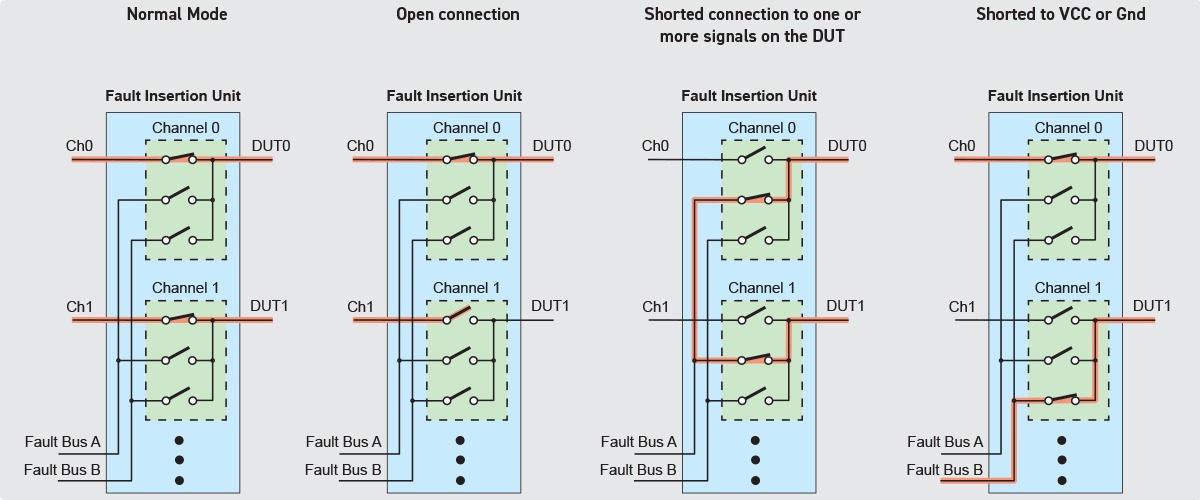
Figure 3 - Open and short fault simulation

Figure 4. Insertion of Resistive Faults
Modular Systems Using PXI, LXI and USB
Several vendors produce dedicated, proprietary, software intensive HILS systems that include hardware fault insertion functionality. These can be highly accurate, but they are also costly, tend to be very large, and customers can find themselves locked to one supplier. Also, the system will be dedicated to one application, so possibly relatively inflexible.
Pickering Interfaces was the first vendor to introduce PXI switching systems explicitly designed to address Fault Insertion applications.
Another approach is to use a standard modular platform – such as PXI – to create a real-time simulation system using best-in-class modules for each function from many suppliers. Pickering Interfaces was the first vendor to introduce PXI switching systems explicitly designed to address Fault Insertion applications. The company manufactures a range of scalable solutions that can be used in place of a patch panel to switch signals from simulated and real-life devices in a HILS system, and can help to considerably simplify and accelerate the testing and verification required.
There may also be instances where the test engineer desires the switching and FIUs to be in a separate chassis to get any electrical switching noise away from the instruments, and the PXI chassis is just a few slots short of what is needed. In this instance, Pickering’s modular LXI/USB chassis support all their PXI modules. In addition, the software drivers are the same whether the modules are in a PXI chassis or the LXI/USB chassis.
PXI Fault Insertion Solutions from Pickering
Single Through Channels
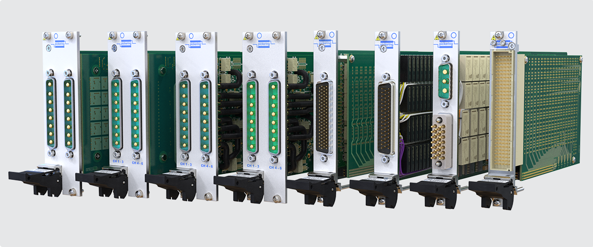
Table 1 shows Pickering’s range of single through channels with standard fault buses.
| Model No. | Signal Channels | Fault Buses | Fault Inputs | Max Voltage | Max Current |
|---|---|---|---|---|---|
| 40-190B | 74, 64 or 32 | 1 or 2 | 4 or 8 | 165 V | 2 A |
| 40-191A | 6 | 2 | 2 | 40 V | 30 A |
| 40-192 | 6 | 2 | 2 | 200 V | 10 A |
| 40-193 | 7 | 1 or 2 | 1 or 2 | 16 V | 20 A, 1 A min |
| 40-194 | 7 | 1 or 2 | 1 or 2 | 16 V | 20 A, no min |
| 40-197A | 34 or 16 | 4 | 8 | 300 V | 2 A |
| 40-198 | 20 | 1 or 2 | 3 or 6 | 250 V | 5 A |
| 40-199 | 10 | 1 or 2 | 2 | 250 V | 10 A |
Differential Signals
Working closely with a leading French aerospace integrator, Pickering developed two signal pair solutions, as shown in Figure 5. These are now available as standard catalog items.
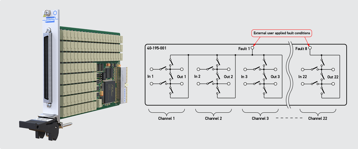
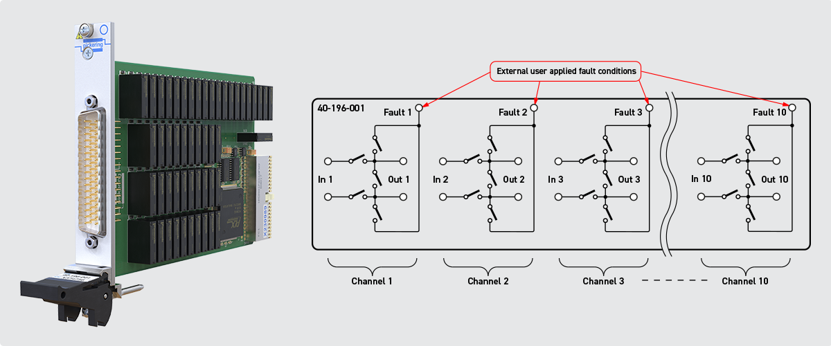
Figure 5 - Signal pair FIU products
Break Out Box
It may become necessary to manually make measurements and introduce faults before writing test code. Most Breakout Boxes (BoBs) used today are not modular and are fixed in configuration, creating test solutions limited in scope. In addition, they have cable configurations that are cumbersome and, in many cases, expensive. Pickering’s low-cost Modular Breakout System combines a BoB feature set with the added flexibility of an FIU. By mating the FIU chassis directly to the BoB, cabling is minimized, creating a more compact, reliable design and improving signal integrity. Also, all cables to the simulation system and the UUT are located behind the front panel of the BoB, creating a simpler front panel that is less prone to damage.
Pickering’s low-cost Modular Breakout System combines a BoB feature set with the added flexibility of an FIU. By mating the FIU chassis directly to the BoB, cabling is minimized, creating a more compact, reliable design and improving signal integrity.
Traditional BoB designs feature a manual potentiometer for creating resistive faults. Pickering can automate this process using one of their programmable resistance modules. The module can be controlled manually through a soft front panel as well as programmatically – speeding up a test process and ensuring repeatability. The software driver from Pickering supports the company’s entire FIU range, so no new software is needed to integrate the new modules.

Figure 6. Ease of connection to Breakout System and FIU
Higher I/O Systems
For more complex systems, Pickering offers a ‘scaled-up’ version of its PXI FIU cards. The 40-592A Fault Insertion Break-Out (FIBO) matrix module is a large-scale high-density switching matrix based on the Pickering BRIC™ format. Fault insertion BRICs are designed for applications requiring the simulation of a variety of faults in complex, high pin count applications involving sensors and control units.
The FIBO Matrix Module is available as either a BRIC4 containing up to 4 daughter cards or a BRIC8 containing up to 8 daughter cards. This allows the X-bus of the matrix to be expanded in multiples of 31 for the 2-pin breakout version or multiples of 20 for the 3-pin breakout version.

Figure 7. Large Scale Simulation is Possible Using the 40-592A BRIC Fault Insertion Break-Out Matrix Module
PXI & PXIe Simulation Solutions from Pickering
Programmable Resistors
Pickering offers over 350 PXI programmable resistor modules, including general-purpose models with up to 48 channels and high precision units featuring better than 0.1 % accuracy and resistance resolution of less than 2 mΩ. Devices may have a built-in calibration port, and RTD and strain gauge simulator models are available.

Thermocouple Simulation
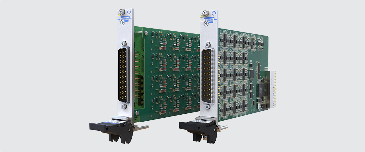
Suitable for sensor emulation in ECU testing, models 41-760 and 41-761 PXI millivolt thermocouple simulator modules provide 32, 24, 16 or 8 channels of accurate low voltage sources. The channels can be operated with one of three voltage ranges covering most thermocouple types.
Additional relays in each channel allow the module to simulate an open connection to each thermocouple. Pickering can also supply connection solutions allowing the easy integration of the thermocouple simulator into your test system.
LVDT/RVDT/Resolver Simulation

Model 4x-670 (available in both PXI and PXIe formats) are single modules that can function as an LVDT, RVDT or resolver simulator. Occupying just one PXI, PXIe or Pickering LXI/USB chassis slot, the module’s programmability means that it minimizes the amount of hardware required. Also, since it sits in a PXI or PXIe chassis alongside a customer’s other instruments, additional control protocols/interfaces are unnecessary, simplifying operation. The 41/43-670 can simulate up to four channels of 5/6-wire LVDT/RVDT or resolver or eight channels of 4-wire LVDT/RVDT simulation. It can operate from an independent or shared excitation signal to each channel for synchronous or asynchronous test. Several models support excitation voltages ranging from 0.25 VRMS to 38 VRMS and frequencies from 300 Hz to 20 kHz, meaning the 41/43-670 family can simulate most LVDT, RVDT, or resolvers currently available. Additional relays on the module allow for open and short circuit simulation on all inputs and outputs.
Current Loop Simulation
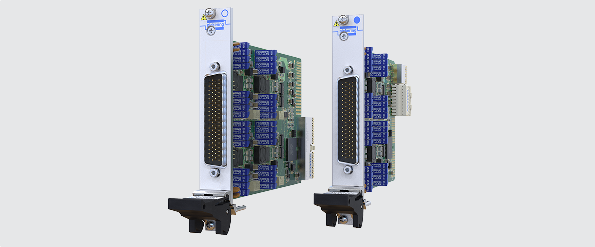
Model 4x-765 analog output/current loop simulator modules available in PXI and PXIe formats simulate industrial control transceivers, utilizing 4–20 mA current loops. The 4x-765 modules also enable slew rates to be programmed so that different sensors can be effectively mimicked. The modules feature multiple output modes, 4–20 mA, 0–24 mA, +/-24 mA, 0-5 V, +/-5 V, and +/-12 mV, improving simulation accuracy and versatility. They include built-in relays for shorts and opens functionality, enabling fault insertion testing on every channel. Devices can also work in Full Isolation mode to avoid ground loops
Battery Stack Simulation
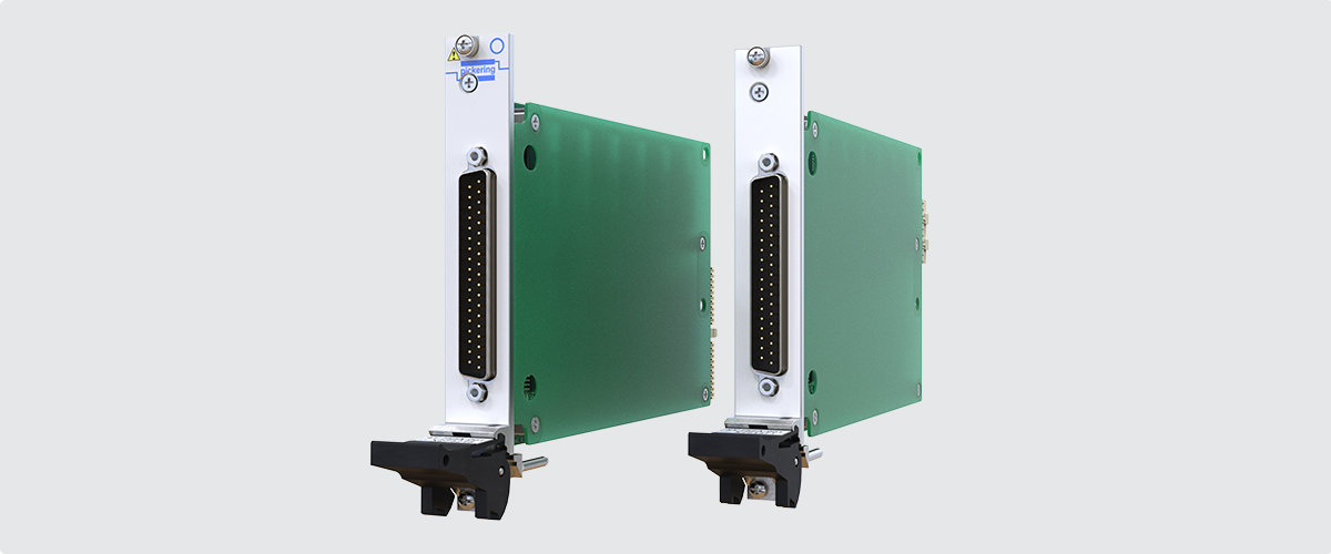
Model 41-43-752A battery simulator modules are available in PXI and PXIe formats. They are ideal for Electric Vehicle (EV) battery stack emulation in Battery Management Systems (BMS) test applications. They are available with two, four or six battery cell simulators per module that are fully isolated from ground and from each other facilitating series connection to simulate batteries in a stacked architecture. Each cell simulator is highly accurate, specified at ±5 mV from 1 V to 7 V. The 750 V isolation barrier allows the modules to be used to simulate lower power battery stacks commonly used for vehicle propulsion. Battery charging emulation is available up to 100 mA.
Conclusion
Simulation and fault insertion are essential in mission-critical, must-not-fail applications typically found in the aerospace and automotive sectors. Many companies in these fields turn to modular PXI-based systems for cost, size, repeatability, versatility and ease of use. Also, they are increasingly using HILS systems on the manufacturing floor as well as in product development. In the production environment, the benefits of modular systems mentioned above are even more apparent.
The emergence of these relatively low-cost, low barrier-to-entry systems also means that other industries can benefit from simulation. Industrial automation is an obvious area that could also benefit. In the future, it is possible to see that, for legal reasons, complex home or office automation systems might also be required to undergo the kind of exhaustive simulation that is currently mainly the preserve of hi-rel systems.


