
Calculating MTBF Figures for Switching Systems
We are occasionally asked what the MTBFs (Mean Time Between Failure) of our switching products. This is a notoriously difficult area since most MTBF calculations are made based on MIL 217, but field experience of failures appears to be almost unrelated to the calculated values for a variety of reasons. This application note is intended to provide some background information on MTBF calculations based on MIL 217 and how they relate to our switching products. There are alternative MTBF methods of calculation of MTBF based on other standards, such as Bellcore/Telcordia, which give different answers to MIL 217, typically much higher MTBF numbers as the reliability data is created for commercial applications. However, the databases for these methods are all quite old.
Requesting an MTBF for a Switching System
We are able to provide MTBF figures for switching systems on request to MIL 217. To do so, please contact customer support. You will be asked to fill out a form.
Application to Switching Modules and Systems
Calculating MTBF for switching modules based on MIL 217 is not straightforward and generally may not align to the field experience of our switching products.
In a typical switching module based on the PXI and LXI, the number of electronic components is relatively small, so their MTBF contribution to the computed MTBF is low. The module design is typically quite tolerant of these components drifting out of specification. Doing a calculation based on the electronic parts will reveal a very high MTBF (much greater than 100,000 thousand hours). Failure of the electronics that support the switches is an unusual event, most service engineers fault finding on a switching module will automatically look for a relay failure because their experience indicates that this is by far the most likely fault.
Reed Relay and EMR Background
We use instrument-grade (sometimes called professional grade) reed relays in our products, which are manufactured by our reed relay division, Pickering Electronics. These are not to be confused with the relays often used by competitors, which are commercial or industrial grade.
Instrument-grade reed relays use Ruthenium contacts to ensure reliable operation at both low currents and voltages and at higher currents and voltages. The contacts are hermetically sealed in a glass envelope, so performance is not sensitive to humidity. High temperatures can cause failures if the reed blades lose their magnetic properties, but generally, it is not a sensitive environmental parameter. If high currents are switched, it will result in the erosion of contact materials and lower the life of the reed relay, a factor that is reflected in the data sheet specification.
The reed blades are operated by a wire coil that generates a magnetic field. Sometimes, early failures can occur because of weakness in the coil or its connections, but generally, the coils are very reliable in service since manufacturing screening eliminates these early failures.
Other than the flexing of the reed blades inside its sealed glass envelope there are no moving parts to wear out. This leads to an extraordinarily long mechanical (low current) life compared to electromagnetic relays. The mechanical life of the reed relays that we use is well in excess of one billion operations. Furthermore, failures during the service interval are rare, so the number of failures per billion operations in the first billion operations is significantly less than in subsequent billions of operations. If a matrix, for example, was being exercised with cross points being randomly closed, it is likely most, or all, of the cross points, will survive at least the billion mechanical operations. A calculation based on, for example, making an assumption on how many operations per hour are performed on each switch does not lead to a sensible MTBF estimate for the matrix as the user is applying end-of-life criteria to the component.
It should be noted that products using either lower-grade reed relays (for example, using rhodium contacts) or electromechanical relays will not necessarily have this performance. They may have failures associated with degraded contact materials even at low signal levels since materials used in lower-grade reed relays have lower-grade contact materials and levels of cleanliness within the glass envelope.
Electromechanical relays are not hermetically sealed and have moving parts that wear out, so they tend to have a lower mechanical life. However, for high current (and power) applications, their larger contacts and wiping action make them more suited since the stress on the part is lower. The same issues of end-of-life aspects apply as for reed relays.
As a consequence of these issues, the manufacturers of complex ATE systems use instrument-grade reed relays in their systems for low-level switching of test points because only instrument-grade reed relays provide the required consistent performance and lifetime that they require, and these are the same components that we use in our PXI modules. Less demanding applications will use EMR's, as will applications requiring higher hot switching capacity or larger carry currents/voltages. (see: Hot switching relays)
Solid State Relays
MIL 217 shows MTTF (Mean Time to Failure) numbers which are orders of magnitude better for solid state relays than for mechanical relays.
Hot Switch Power Impact On Life
As the loaded power of the reed relay (or, for that matter, any relay) increases, there comes a point where the mechanical life is not the determining factor in switch life. As the current or voltage is switched, arcing and contact material migration will start to damage the contact area and limit the life, the degradation being current, voltage and power dependent.
For a typical reed relay with a low power (mechanical) life above 1 billion operations, the lifetime is likely to reduce to, for example, 5 million operations at its rated load (voltage, current or power). Lifetime will be higher if the test system design avoids hot switching since arcing and inrush currents from intended or stray capacitive loads (even including cables) are minimized. The operating conditions are absolutely critical in estimating the lifetime of the relay in service.
There is no convincing data on how a relay with time-varying loads behaves, even though MIL 217 does contain some assumptions in this area. Estimating life under these conditions is not as simple as weighting the switching operations according to load conditions.
It should also be remembered that under hot switching conditions, the user's cabling may also significantly impact life because the cable may add a reactive load (e.g., capacitance) to the load seen by the relay.System Debugging - A Major Cause of Early Failures
One problem that frequently occurs is during the debugging phase. Programming or construction errors outside the switch matrix can result in accidental shorts being introduced which overload or damage the relays during the commissioning of the system. Our experience has been that early failures are dominated by such factors, the most common being relay contacts welded together because of hot switching of heavy currents (for example, across a power supply or providing power to a large capacitive load). The switching modules are at their most vulnerable during this phase of their use, and these failures are not included in any MTBF calculation. The worst scenario is, of course, where the contacts are damaged but still function.
Relay Operation Counting
Some products may use counters to indicate how many times a relay has been operated to advise the user to consider relay replacement as a maintenance item. Given that almost three orders of magnitude variation in life according to loading factors occur, this is hard to recommend as a good practice. The user would need to know what the load was for each operation and then have some representative model of how that impacts service life.
Prematurely replacing relays can induce more faults through component stress during service (particularly surface-mounted devices), and repeated intervention may render a perfectly good switching system unusable. The relays should be replaced because they are failing or have already failed—there is much to recommend the practice of leaving it alone if it is working.
For reed relay-based designs, we do not support relay operation counting because it does not perform a useful function unless the user makes extraordinary efforts to estimate load conditions (perhaps through the IVI drivers) for each operation. Most users do not have the luxury of enough resources or time to do it well enough to make a difference or a useful prediction.
Diagnostic Test Tools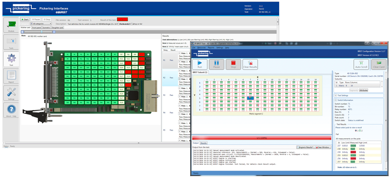
A much more useful approach to servicing is to have a diagnostic test tool that can identify faults in a matrix. we offer two tools for diagnosing relay failures, BIRST (Built-in Relay Self-Test and eBIRST test tools, where the contact is rated at 2A or less. The tools will identify the faulty cross point or isolation switch so that the user can replace it. eBIRST requires the use of external tools, and BIRST is built into some of our matrix designs. Here are some additional articles on these tools:
The use of leaded components in preference to surface mount relays reduces the stress on adjacent components when servicing is performed.
The larger physical size of VXI and GPIB-based switching modules allows them to have diagnostics systems built into them to permit self-testing of the module switches, but these systems reduce the density of the switching system and increase their complexity and cost.
Summary
Calculating MTBF numbers for relay assemblies is not straightforward, and the results need to be treated with caution. The user must state the conditions and assumptions used to make the calculation.
The use of the most appropriate high-quality products can improve system reliability, but the actual service life calculation can lead to misunderstandings about life expectancy.
Relay counting methods of predicting future failures are particularly unreliable in anticipating failures, and premature servicing of relays can cause more failures than the replacement exercise was designed to reduce. It is much more effective to rely on good diagnostic tools being available, such as BIRST and eBIRST. These tools will reduce the risk of replacing relays unnecessarily and avoid making errors in diagnosing problems.

