
Pickering Card Topology
Note:
- This discussion is most pertinent to our low-level drivers: pipx40, pilpxi and piplx, where the objective is the control of switch entities.
- The IVI driver pi40iv utilizes a distinct approach to routing between endpoints, making portions of this discussion less applicable to that particular driver.
Our cards feature multiple switches and other functions thoughtfully arranged into functional groups, such as multiplexes or matrices, for optimal performance and organization. The firmware of a Pickering card organizes its switches into logical groups, referred to as "subunits." This term represents the structured grouping designed for clarity and efficiency.
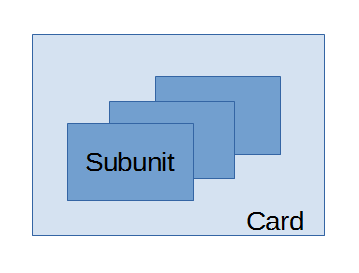
To control a switch, the user must first identify the subunit where the switch is located.
In some cases, a card may contain only a single subunit, while in others, multiple subunits may be present. If there's any uncertainty, consult the product manual for detailed information on the subunit structure.
Within the driver interface, each subunit consists of multiple bits—one for each switch—organized into one or more 32-bit words.
The driver offers functions to control either a single bit (one switch) or all bits within a subunit in a single operation.
As a result, each function requires details about the card and its subunit, followed by the specific switch or switches to be controlled.

