
Contents
16 Feb 2026 • 10 minutes
Multi-Gig Automotive Ethernet Validation: Applications for 10GBASE-T1 MEMS Fault Insertion
Accelerate validation with automated fault insertion testing for 10GBASE-T1 Automotive Ethernet. Providing practical guidance for test engineers working with Advanced Driver Assistance Systems (ADAS) and multi-gigabit automotive Ethernet networks.
Introduction
The advancement of Advanced Driver-Assistance Systems (ADAS) and autonomous driving (AD) technologies has established multi-gigabit data transmission as a fundamental requirement of contemporary vehicle architecture. Automotive Ethernet, specifically the 10GBASE-T1 standard (IEEE 802.3ch), serves as the primary backbone for high-throughput, low-latency communication required by sensor-fusion and centralized compute ECUs. While this standard delivers the necessary bandwidth, it introduces substantial validation challenges. Ensuring the functional safety and reliability of these networks under all possible real-world fault conditions is a critical concern for automotive test engineers.
Traditional validation methods rely extensively on physical road testing and are no longer viable due to the combinatorial complexity of potential network failures. This creates a significant bottleneck in the development lifecycle, resulting in delayed time-to-market and increasing validation costs. Automated fault insertion testing in controlled laboratory environments provides a structured, repeatable, and cost-effective alternative.This document details the application of Micro-Electromechanical Systems (MEMS)-based Fault Insertion Units (FIUs) for validating up to 10GBASE-T1 Automotive Ethernet links. It examines Pickering's 40/42-205 family of PXI/PXIe MEMS FIU modules (see Figure 1), which are designed to address the signal integrity and performance requirements of multi-gigabit data rates. We also explore the technical advantages of MEMS switching technology—including high bandwidth, extended operational life, and fast switching speeds—and identify key engineering applications where these units provide maximum benefit.

Figure 1 – 40/42-205 Switching Topology (4-channel version illustrated).

Figure 2 – Menlo Micro’s MEMS Ideal Switch.
The primary applications discussed are:
- ADAS/AD ECU Validation: Comprehensive testing of electronic control units (ECUs) responsible for sensor fusion and decision-making.
- High-Resolution Sensor Link Verification: Ensuring the reliability of data links from critical sensors, such as LiDAR, RADAR, and high-definition cameras.
- Zonal Architecture Gateway Testing: Validating the robustness of zonal gateways that aggregate data from multiple domains before transmitting it to the central computer.
This document examines these applications and provides test engineers and managers with technical guidance for integrating MEMS FIUs into their validation workflows. The result is reduced test cycle times, improved defect detection, and measurable return on investment, ultimately accelerating the deployment of reliable autonomous vehicle technologies.
Automated MEMS-based fault insertion cuts fault-test cycle time from minutes to seconds, while improving first-pass yield
The Validation Challenge in High-Speed Automotive Networks
For more than four decades, the automotive industry has pursued advancements in active vehicle safety. Systems such as Anti-lock Brakes (ABS) and Blind Spot Information Systems (BLIS) have substantially improved driver safety. Today, the focus has shifted towards fully autonomous driving, where the vehicle assumes complete control, and the driver becomes a passenger. This evolution, defined by the Society of Automotive Engineers (SAE) J3016 standard, is categorized into six levels of driving automation, from Level 0 (no automation) to Level 5 (full automation). As of 2024, production vehicles have achieved SAE Level 2+ and Level 3, with substantial development requirements remaining to reach higher levels of autonomy.
Achieving this requires complex integration of electronic subsystems that perceive the vehicle’s environment and make real-time decisions. This paradigm is built on a foundation of high-speed data transmission. A typical ADAS-equipped vehicle utilizes a suite of sensors—including video and infrared cameras, ultrasonic sensors, RADAR, and LiDAR—all of which generate substantial volumes of data. When combined with high-definition digital maps, the data flowing to the central ADAS controller can reach multi-gigabyte per second rate.
This data volume necessitates a fast, synchronous, secure, and reliable network architecture. A failure in the data communication path can have immediate consequences for vehicle safety. Therefore, the test and validation strategies of these networks must be as advanced as the systems themselves. The challenge for test engineers is to comprehensively verify network integrity and the system’s response to any potential interconnection fault. This whitepaper focuses specifically on fault testing the 10GBASE-T1 Automotive Ethernet channels that form the communication backbone of modern ADAS control modules.
The Rise of 10GBASE-T1 Automotive Ethernet
To manage the high data throughput required by ADAS, the industry has adopted the IEEE 802.3ch standard, commonly referred to as 10GBASE-T1 for Automotive Ethernet. This standard enables 10 Gb/s data transmission over a single shielded twisted-pair cable, operating in full-duplex mode where signals are transmitted and received on the same pair. This approach offers a substantial advantage over legacy automotive networks, such as CAN and FlexRay, which lack the bandwidth required for sensor-fusion applications.
Vehicle network architectures typically employ multiple 10GBASE-T1 channels arranged in a star configuration, connecting various sensor arrays and subsystems to a central ECU or a domain controller. This topology provides inherent fault isolation; a failure on one channel, such as a LiDAR unit, can be managed by the system without affecting the operation of other critical sensors, like RADAR. This separation simplifies system-level decision-making during fault events.
From a test perspective, design verification and production testing must confirm that any fault on one or more of these Ethernet channels is correctly detected and results in a predictable system response, whether it’s graceful degradation of functionality or complete system shutdown. The verification process must cover every wire of every channel, simulating a comprehensive range of potential real-world failures.
The Problem: Limitations of Traditional Validation & EMR-Based Fault Insertion
The validation of ADAS for high levels of functional safety (e.g., ASIL D) requires demonstrating reliability with extremely high confidence. Statistical analysis indicates that proving this reliability through physical road testing would require accumulating approximately 220 million kilometers of failure-free driving—a practical and financial impossibility. This has driven the industry toward laboratory-based validation methodologies, including Hardware-in-the-Loop (HIL) simulation and fault insertion.
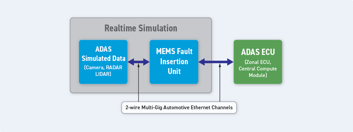
Figure 3 – The position of fault insertion in a simulation system.
Fault Insertion Units (FIUs) are positioned between the test system (simulator) and the Device Under Test (DUT), such as an ADAS ECU. In their default state, they pass signals through transparently. When activated, they introduce various fault conditions to the signal paths. Historically, these FIUs have been constructed using electromechanical relays (EMRs). While effective for lower-speed signals like CAN or LIN, EMRs present substantial challenges for high-speed differential signals like 10GBASE-T1 Ethernet:
- Signal Degradation: EMRs introduce impedance discontinuities, stubs, and parasitic capacitance that degrade signal integrity. At the multi-gigahertz frequencies of 10GBASE-T1, this degradation can lead to bit errors, closed eye diagrams, and link instability, making it difficult to distinguish between genuine DUT failure and test-induced artifacts.
- Limited Bandwidth: The physical construction of EMRs inherently limits their bandwidth. They are not designed to reliably pass signals with frequency components extending into the 4-5 GHz range, which is necessary for 10GBASE-T1.
- Slow Switching Speed: EMRs have switching times in the millisecond range. This can be insufficient for test scenarios that require precise timing or rapid cycling between normal and faulted states.
- Limited Operational Life: EMRs have finite mechanical life, typically measured in millions of cycles. In automated test environments running continuous regression tests, this lifespan can be exhausted rapidly, leading to increased maintenance and system downtime.
These limitations render traditional EMR-based FIUs unsuitable for the rigorous validation of multi-gigabit automotive networks, thereby creating a need for more advanced switching solutions.
The Solution: High-Performance MEMS-Based Fault Insertion Units
To address the challenges of testing high-speed data links, a new approach to fault insertion is required. MEMS switching technology provides the necessary performance characteristics for multi-gigabit applications. The 40/42-205 family of Fault Insertion Switches leverages this technology to deliver a solution tailored for 10GBASE-T1 validation.
Impedance-controlled MEMS FIUs deliver over 3 billion operations per relay and built-in cycle counting, enabling proactive maintenance and maximizing EoL test station uptime.
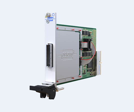
Pickering’s 40/42-205 10GBase-T1 MEMS Fault Insertion Switch Module
|
|
Available in both PXI (40-205) and PXIe (42-205) formats, these modules feature 4 or 8 impedance-matched channels capable of addressing 10GBASE-T1 requirements. The technical advantages of the MEMS-based design include:
- High Bandwidth and Signal Integrity: The MEMS switches are designed for high-frequency performance, with bandwidth capable of supporting up to 10 Gb/s data rates. This ensures that the FIU itself does not become a bottleneck. The modules feature low insertion loss and voltage standing wave ratio (VSWR), preserving the integrity of the 10GBASE-T1 signal as it passes through to the DUT.
- Extended Operational Life: MEMS switches have operational life exceeding 3 billion cycles. This represents an order of magnitude improvement over EMRs, making them suitable for the repetitive, high-throughput demands of automated testing environments. Relay cycle counting is included to proactively alert test engineers when a module is nearing end-of-life
- Fast Operation: With switching speeds in the microsecond range (subject to system overhead), MEMS FIUs can simulate intermittent or transient faults with high fidelity
Comprehensive Fault Simulation: The 40/42-205 modules can simulate the full range of fault conditions required for automotive validation, including:
- Open circuit on an individual wire or the entire channel
- Shorts between the two wires of a differential pair
- Shorts from any wire to an external VCC (e.g., battery voltage) or GND
- Shorts between wires of different channels
- Partial or resistive shorts via external fault buses
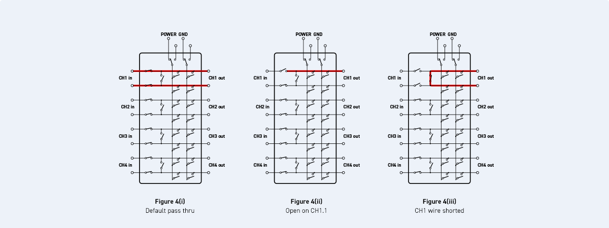
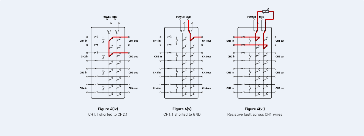
In Figure 4(i), the FIU is in the default mode of operation (channels commanded to close), where all signals are passed through. In Figure 4(ii), an open circuit is being simulated on channel 1; in Figure 4(iii), there is a short between channel 1 wires; in Figure 4(iv), there is a pin-to-pin short between channels 1 and 2; and in Figure 4(v), a short-to-ground fault simulation is produced on channel 1, and in Figure 4(vi), a resistive fault is simulated between channel 1’s wires.
This combination of performance attributes makes MEMS-based FIUs the optimal solution for creating reliable and repeatable test environments for 10GBASE-T1 networks.
Key Engineering Applications for 10GBASE-T1 MEMS FIUs
The benefits of MEMS FIUs are most pronounced in applications where high data rates and absolute signal integrity are non-negotiable. For automotive test engineers, three primary applications stand out.
Application 1: ADAS/AD Central Compute ECU Validation
The Challenge: The ADAS/AD central compute ECU functions as the primary processing unit of the autonomous system. It aggregates data from all vehicle sensors, runs perception and decision-making algorithms, and issues commands to actuators. This ECU typically has multiple 10GBASE-T1 Ethernet ports to receive high-bandwidth data streams from various sensors simultaneously. Validating this ECU requires systematically testing the physical layer (PHY) of every Ethernet port to ensure correct response to any conceivable link failure. The system must be able to detect a lost or corrupted link, flag the error, and execute a safe fallback strategy.
PXI/PXIe FIUs support high-density, multi-channel testing for zonal gateways, sensor fusion ECUs, and central compute—validating interoperability across multi-vendor PHYs at 10GBASE-T1.
MEMS FIU Application: A PXI chassis populated with 40/42-205 MEMS FIU modules can be positioned between an Ethernet traffic generator/analyzer and the central ECU. Each 10GBASE-T1 link to the ECU is routed through a channel of an FIU. An automated test sequence can then programmatically inject faults onto each link.
Specific Test Scenarios:
- Single-Point Faults: An open circuit is created on one wire of a single LiDAR input. The test verifies that the ECU’s corresponding PHY detects the loss of link status (LPI) and that the central processor correctly identifies the faulted sensor and excludes its data from the sensor-fusion algorithm.
- Latent Multi-Point Faults: A resistive short-to-ground is applied to a camera link, causing intermittent packet loss, but not complete link failure. Simultaneously, a full open-circuit fault is applied to a RADAR link. This tests the ECU’s ability to manage multiple, concurrent faults of varying severity, and prioritizes its response based on functional safety requirements.
- Power-Related Faults: A short-to-battery (Vbatt) fault is injected into one of the Ethernet channels. This simulates a wiring harness failure, where a power line comes into contact with a data line. The test must verify that the ECU’s PHY is not damaged, and that the system can safely handle the condition without propagating the high voltage to other components. The power handling capability of the MEMS FIU is critical for this test.
The MEMS FIU’s fast switching allows for simulation of “glitching” or intermittent connections, which are common real-world failures and difficult to reproduce with manual methods or slower EMRs.
Application 2: High-Resolution Sensor Link Verification
The Challenge: High-resolution sensors, particularly LiDAR and 4K+ cameras, function as the primary sensing elements of an autonomous vehicle. The data links from these sensors to the ECU are safety critical. Any corruption or loss of this data can lead to incorrect perception of the environment. The physical link, including cables and connectors, is exposed to vibration, temperature extremes, and moisture, making it susceptible to degradation over the vehicle’s lifetime. Test engineers must verify that the link maintains its integrity and that the system can detect subtle degradations before they lead to catastrophic failure.
Software-driven fault libraries and logged results per serial number create consistent execution and evidence for ISO 26262, SOTIF, and ASPICE—reducing audit risk and variance across lines/sites.
MEMS FIU Application: In this scenario, the DUT could be the sensor itself or the entire link, including cabling. The FIU is used to precisely degrade the signal path to determine the operational margin of the link.
Specific Test Scenarios:
- Intermittent Connection Simulation: Using the FIU’s fast switching speed, the test system can rapidly cycle a connection open and closed to simulate a loose connector. This helps determine if the sensor’s and ECU’s PHYs can re-establish the link quickly and reliably (fast link-up time) without requiring a full system reset.
- Characterizing Fault Detection Thresholds: The FIU can be used with an external resistive network connected to its fault bus. By programmatically stepping through different resistance values for a pin-to-pin or pin-to-ground short, engineers can precisely characterize the threshold at which the ECU’s diagnostic routines detect and report a fault. This is essential for avoiding false positives from minor, non-critical signal variations.
The high bandwidth of the MEMS FIU ensures that the tests are accurate and repeatable, as the test instrument itself does not introduce signal integrity issues.
Application 3: Zonal Architecture Gateway Testing
The Challenge: Contemporary vehicle architectures are transitioning towards a zonal concept. In this design, zonal gateways are positioned in different physical areas of the vehicle (e.g., front-left, rear-right). These gateways aggregate data from local sensors and ECUs (using protocols like CAN, LIN, and lower-speed Ethernet) and then transmit the consolidated data to the central compute ECU over a high-speed 10GBASE-T1 backbone. The zonal gateway represents a critical point of failure; its validation requires testing both the various low-speed inputs and the high-speed Ethernet uplink.
MEMS FIU Application: The test setup for a zonal gateway involves a multi-pronged approach. EMR-based FIUs can be used to inject faults on lower-speed CAN and LIN inputs, while a 40/42-205 MEMS FIU is used for the 10GBASE-T1 uplink. The entire system is orchestrated from a single PXI controller.
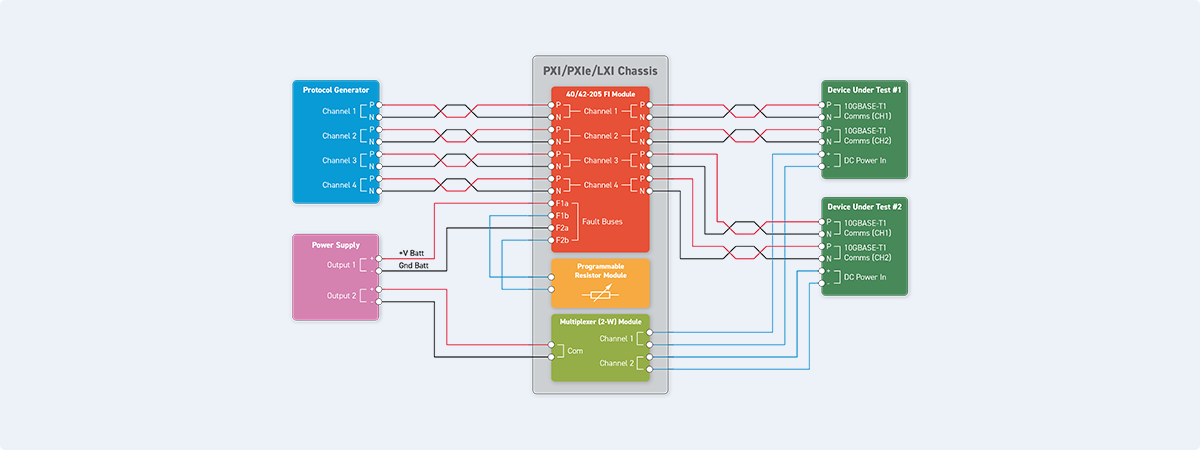
Figure 5 – Typical FIU implementation for Multi-Gigabit ADAS ECU validation.
Specific Test Scenarios:
- Uplink Failure: The MEMS FIU injects a fault (e.g., an open circuit) on the 10GBASE-T1 uplink. The test verifies that the zonal gateway correctly detects the loss of communication with the central computer and enters a pre-defined safe state. This may involve broadcasting specific messages on its local CAN buses to inform other local ECUs of the failure.
- Error Propagation Testing: A “babbling idiot” fault is created on one of the gateway’s CAN inputs. The test engineer must verify that this low-level fault does not corrupt the data being transmitted over the 10GBASE-T1 uplink and cause a wider system failure.
- Full System Stress Test: The test system injects faults on multiple low-speed inputs while simultaneously stressing the 10GBASE-T1 uplink by injecting intermittent faults with the MEMS FIU. This complex scenario tests the gateway’s processing capacity and its ability to manage a “fault storm” without crashing or behaving unpredictably.
Using a combination of EMR and MEMS FIUs in a unified PXI-based system provides a scalable and cost-effective solution for comprehensive zonal gateway validation.
System Integration: Building a Robust Test Environment
Integrating a 10GBASE-T1 MEMS FIU into a test system requires careful attention to the entire signal path to maintain signal integrity. Due to the high frequencies involved, cabling and connectors are critical components.
Utilizing a common cable interface eliminates manual setup, reduces equipment overhead, and accelerates operating timelines while decreasing rework/scrap through earlier, more reliable defect detection.
The front panel of the 40/42-205 module features a high-density, high-speed connector (SAMTEC Eye Speed®). To assist with test system interfacing, a breakout assembly is used to access the individual differential pairs plus fault bus connections. This unit distributes the Ethernet signals from the FIU to standard high-frequency connectors (Pickering’s standard breakout assembly 40-205-901- 800 uses Rosenberger H-MTD connectors, but other automotive Ethernet connector interfaces can be supported on request).
Critical considerations for system integration:
- Cable Lengths: All high-frequency cables—from the FIU to the interface board, and from the interface board to the DUT—should be as short as possible to minimize signal loss and degradation.
- Impedance Matching: Use impedance-controlled cables (100 Ω differential) throughout the signal path
- Calibration and De-embedding: For highly sensitive measurements, it may be necessary to measure the S-parameters of the entire test fixture (FIU, cables, interface board) and use de-embedding techniques to mathematically remove their effects from the final measurement of the DUT.
By following these practices, test engineers can build a reliable and accurate automated test system that leverages the full capabilities of MEMS fault insertion technology.
Conclusion: Accelerating Reliability with MEMS-based Fault Insertion
The validation of 10GBASE-T1 Automotive Ethernet networks is a significant challenge in developing next-generation ADAS and autonomous vehicles. Traditional electromechanical relay (EMR)-based fault insertion methods are insufficient for multi-gigabit signals, forcing engineers to choose between incomplete laboratory testing and resource-intensive physical road testing.
Pickering’s 40/42-205 family of MEMS-based Fault Insertion Units (FIUs) provides a solution to this problem. These modules, in conjunction with Pickering’s specifically designed matching breakout assemblies, offer high signal integrity, sufficient bandwidth for 10GBASE-T1, extended operational life, and fast switching speeds. This enables test engineers to perform comprehensive, repeatable, and automated fault insertion testing on 10GBASE-T1 links within a laboratory environment.
Key engineering applications, such as validating central compute ECUs, verifying high-resolution sensor links, and testing zonal gateways, demonstrate the critical role these FIUs play in ensuring the functional safety and reliability of the vehicle network. By integrating MEMS FIUs into HIL and bench test systems, engineering teams can achieve several objectives:
- Increased Test Coverage: Systematically test for a wide range of fault conditions that are difficult or impossible to replicate with traditional methods.
- Improved Defect Detection: By introducing precise and repeatable fault conditions, engineers can identify potential hardware and software weaknesses early in the development cycle, reducing the risk of failures in production or in the field.
- Accelerated Validation: The high reliability and fast operation of MEMS technology enable more rapid and automated test cycles, leading to improved efficiency and adherence to project timelines.
By adopting MEMS-based fault insertion, development teams can enhance their testing processes and ensure the delivery of robust and reliable systems for modern connected and autonomous vehicles.


