BMS Functional Verification... in 15 Seconds
MSL Circuits verifies EV battery management systems' performance and safety features thanks to products and technical support from Pickering Interfaces.
| In late 2020, MSL Circuits, an ALL Circuits company and renowned France-based engineering manufacturing services provider, won a tender for the manufacture and test of battery management systems. The order was with a major automotive company that wanted each BMS to be functionally verified as they came off the production line at a rate of four per minute. Having devised a test methodology, MSL turned to instrumentation company Pickering Interfaces for PXI battery simulation modules, chassis and support. |
A battery management system (BMS) is a core element within a battery pack, as used in an electric vehicle (EV), hybrid or plug-in derivative, and many other vehicle types that have either purely or partially electric drivetrains.
A battery pack typically contains a number of battery modules, which in turn contain several lithium-ion (Li-ion) cells. The most common cell form factor is cylindrical, and cells are traditionally arranged in groups of 12 or 24. The cells and modules are connected in series and parallel combinations to release the stored electrical energy to produce the desired performance for the vehicle.
The BMS has a number of roles. These include providing state-of-charge (SoC) and state-of-health (SoH) data to the vehicle’s ECU and other systems. Its main management roles are to optimize battery performance and provide protection in the event of cells failing.
Functional verification is essential for any BMS as it must meet the safety requirements stipulated in industry standards such as ISO 26262.
Also, as an EV’s battery pack is effectively its defining component, determining the vehicle’s maximum range and acceleration, for example, it must be reliable and have as long a life as possible. From a cost point of view, the battery pack equates to about one-third of that of the vehicle, so manufacturing (and test) costs need to be tightly controlled.
To align with the electrical architecture of a typical EV battery pack, most BMSs comprise a controller and several responder units – see figure 1.

Figure 1 – Above is a simplified BMS architecture in terms of its components and functions.
The controller unit is responsible for:
- Monitoring overall power levels and protecting against overcurrent to and from the battery pack.
- Accepting temperature readings/data from all responder units.
- Controlling safety/contactor switches with all responder units, in case any need to be isolated in the event of overtemperature.
A responder unit is responsible for:
- Temperature monitoring. Li-ion cells are sensitive to overcharging (which reduces efficiency and life) and rapid discharging, both of which can result in thermal runaway and fire.
- Cell balancing. This ensures that cells connected in series receive the same charge. The most common method of cell balancing is passive (or charge shunting), in which cells that have received their full charge are protected from receiving further charge. Essentially a resistance is placed in parallel with the cell that needs protecting. Most of the current will then bypass that cell to reach and charge others in the series stack.
“In order to verify that a BMS from our production line functions correctly, we knew we would need to start by verifying the functionality of the responder units within the modules and, to do that, we would need to simulate cells being charged, discharged… and failing,” commented Manuel Dos Santos, MSL Circuits’ BMS Test Bench Architect. “Known good [functionally verified] responder units will be used to verify control units.”
Challenges & Solutions
MSL Circuits’ requirements were for eight BMS test stations, that could test either controller or responder units.
Core to the tests would be the ability to simulate multiple cells at once but for the test stations to be as compact as possible. Also, test accuracy and speed would need to be high and, in this respect, a test time of 15 seconds per BMS (off the production line) was set as a benchmark. In searching for a solution, MSL recognized the PXI form factor would best serve their needs (as LXI and GPIB communications are too slow) and contacted Pickering Interfaces to discuss chassis and modules. Regarding the latter, Pickering’s PXI 6-Channel Battery Simulator Module, model 41-752-001 (see figure 2), was an obvious choice.

Figure 2 – Above, (left) Pickering Interfaces’ PXI 6-channel battery simulator module and (right) its functional block diagram.
The simulator is effectively a power supply module with six isolated outputs, each capable of supplying up to 7VDC at up to 300mA. Each channel can also sink current, and therefore behave as a load just as a battery cell does when being charged.
Also, each channel is fully isolated from ground and from adjacent channels, allowing them to be connected in series to simulate cells in a stacked architecture. A 750V isolation barrier allows the module to be used as a lower-power version of a battery stack representative of those used for vehicle propulsion.
Each channel provides independent power and sense connections, allowing the battery simulator to sense a remote load and correct for wiring losses. The battery simulator is designed to respond to dynamic loads, minimizing the need for local decoupling capacitors at the load.
A control line on the user connector allows the user to shut down all battery simulator channels with one signal. Multiple control lines can be linked together to provide an easy way of inhibiting the output when using several series-connected modules. This also provides a means of automatic shutdown when connectors are removed.
“Our PXI 6-channel Battery Simulator Module is a standard part, launched in 2010, as we’ve been serving a number of sectors in which battery management is needed for some time now,” notes Michael Crespin, Pickering Interfaces’ Sales Director for France. “However, MSL required greater accuracy than was standard for our product at that time. Specifically, MSL wanted the output voltage emulation accuracy to be ±2.5mV and the read accuracy to be ±10mV.”
To meet MSL’s requirements, Pickering Interfaces’ highly experienced product development team in the UK — a team that comprises hardware and software engineers and manufacturing specialists — added new voltage and current read back circuitry. Impressively, the product revision took just six months and was undertaken during the team’s other work. Note: Pickering Interfaces typically launches five to 10 new product families per year, with a similar number of upgrades being made to existing products during the same timeframe.
As for the chassis, MSL initially wanted a standard PXI version. However, Pickering Interfaces recommended a hybrid chassis (model 42-925-001) that can take PXI or PXIe modules. The main driver behind the recommendation was availability, as the hybrid has a shorter lead time. However, the solution will also give MSL more flexibility in the future.
Test Environment
As mentioned, MSL’s goal was to have universal BMS test stations, capable of verifying both controller and responder units. To this end, MSL worked with Virginia Panel Corporation (VPC) to create the station shown in figure 3 and two fixtures, one for testing controller units and one for testing responder units.
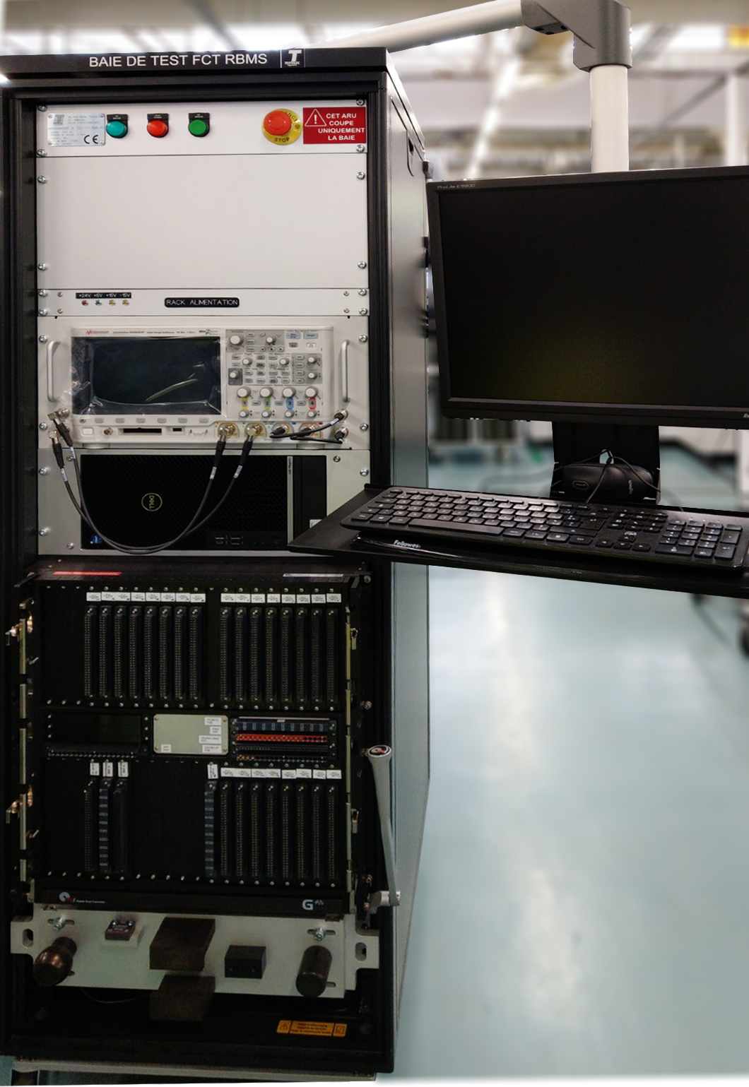
Figure 3 – Above is the backend of MSL’s BMS test station. It contains the battery cell simulator modules, enhanced by Pickering Interfaces to have an output voltage emulation accuracy of ±2.5mV and a read accuracy of ±10mV.
Front end fixtures can be configured for verifying either BMS controller units (up to four at a time) or responder units (up to 10 at a time – as shown in figure 4), and VPC contributed greatly to the architecture of, and integration within, the chassis to make this possible.
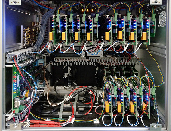
Figure 4 – Above is a front-end fixture for verifying BMS controller units against reference responder units (12 in this instance) that have already passed their functional verification tests. Each responder unit connects to two 6-channel battery simulator modules, meaning a total of 144 cells are being simulated.
“It would have been easier and cheaper to create a backend with a dedicated BMS responder unit test,” recalls Dos Santos, “but we knew from the outset we wanted modularity, flexibility, and the ability to connect different fixtures. Emulated cell connections are specific to the battery model installed in the fixture. In this way, the test station remains generic, with a total of 144 independent battery simulator modules available.”
All tests were written in Marvin Test’s popular ATEasy software. It was used as a test sequencer. Pickering Interfaces provided MSL with the libraries, drivers and a software front panel (SFP) that enabled the EMS to develop and prove their tests early on in the project. Also, Pickering Interfaces’ software is capable of multithreading, and it is possible to drive four battery simulator modules (i.e., simulate 24 cells) at once.
As for the tests being performed, BMS responder unit tests are:
- Cell measurements. For this, all simulators are set with different voltages. These are read by the BMS responder and communicated via UART to the BMS controller. A PC connected via CAN bus then compares the recorded voltages against reference ones. It is a relatively simple Pass/Fail test, but it verifies that everything between the cell and the BMS responder’s CAN bus interface is functioning correctly.
- Cell balancing. For this, all simulator cards’ channel outputs are again set with difference voltages. Then, a command from a BMS controller is sent to the responder units to commence cell balancing. The balancing current is read by the test station.
- Cell temperature. Each power module contains a number of thermistors. The responder unit’s ability to read these (under ambient / room temperature conditions) is verified.
As mentioned, multithreading allows four cards to be driven at once – which is ideal in instances where a single instrument is going to perform the same test on multiple devices under test. In this case, the test software can interact with 120 simulated cells in just a few milliseconds, whereas single-threaded tests and the use of a slower bus (LXI or GPIB, for example) would take tens of seconds.
Fully Charged
At the time of writing, Pickering Interfaces has delivered hardware for eight test stations. MSL has configured four for testing BMS controller units and four for testing BMS responder units.
All commissioning work is complete, and MSL has entered into low-volume production, with high-volume production planned for early 2023, at which time all BMS test stations will be running 24/7.

Above is MSL Circuit’s test area for battery management systems as they come off the production line.
As for the test target time? To functionally verify a full BMS (i.e., the controller unit and all its responder units)
takes around 60 seconds. With four test stations available, testing BMSs as they come off the production line at
a rate of four per minute (15 seconds each) has been met.
Manuel Dos Santos concludes: “This has been an amazing project, rich with collaboration from numerous parties. We were particularly impressed that Pickering Interfaces already had a dedicated battery simulator module as a standard product and the speed with which they were able to modify it to meet our needs.”
In summary, MSL Circuits has a highly accurate and extremely fast solution for verifying the functionality of BMS controller and responder units. Also, the solution is future-proofed thanks to the use of Pickering Interfaces’ hybrid PXIe chassis.