Using the Voltage Sense Connections on a Power Supply
Power supplies often have voltage sense connections. This page explains why they are used.
The image below shows the connection of a power supply to a resistive load with and without a sense connection.
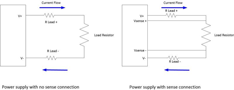
The load is connected using copper wires in each case, those copper wires have a resistance.
If for example a lead has a resistance of 0.1 Ohms and the load resistor is drawing 1A then R Lead + and R Lead - each have a voltage drop of 100mV. If the connection is made with no sense connection then the voltage supplied to the load resistor will be 200mV lower than expected. This may or may not be a significant issue for the user.
If the power supply is connected with the sense wires connected the sense wires provide the power supply with a measurement of the voltage at the resistor, no current flows in the sense wires because the sense connections have a high input impedance. As a result the resistance of the sense wires can be high without having an impact. The power supply is forced by the sense lines to supply the correct voltage to the resistor and the voltage across V+ and V- (in the example given) is set 200mV higher.
If the load current changes then the power supply will have to keep adjusting its output voltage to correct for the loss in the connection resistance. This can lead to transients voltage being generated which are normally managed by having local capacitors in the load. See more information on transients behavior here >>.
Connection Lead Resistance
The resistance of the connection to the load can be reduced by either decreasing the wire length or increasing the wire gauge. In a test system the resistance can also include the resistance of a switching system used to route the power supply, this is controlled by the switching system vendor. For that reason the switching system may have to handle power supply distribution with four paths, 2 connecting the power and two connecting the sense.
Even with a sense connection it may be wise to minimize the connection resistance since excessive path resistance can lead to the generation of voltage transients.
For convenience the table below gives some useful information on the approximate resistance of selected wire gauges.
| Wire Gauge in AWG | Resistance per meter |
| 26 | 133.9 mOhms/m |
| 24 | 84.2 mOhms/m |
| 22 | 52.9 mOhm/m |
| 20 | 33.3 mOhm/m |
| 18 | 20.9 mOhm/m |
| 16 | 13.2 mOhm/m |
| 14 | 8.29 mOhm/m |
| 12 | 5.2 mOhm/m |
| 10 | 3.28 mOhm/m |